
 WhatsApp: +86 16626708626
 Email:
  Phone: +86 16626708626
Description
Key Technical Specifications
- Form Factor: PCI 32/64-bit, 33/66 MHz, 3.3 V or 5 V signaling
- Memory: 128 MB SDRAM Reflective Memory with parity
- Network Topology: Fiber-optic ring (daisy-chain), up to 256 nodes
- Data Rate: 43 Mbyte/s (4-byte packets) to 174 Mbyte/s (64-byte bursts) non-redundant
- Serial Link Speed: 2.12 Gbaud
- Latency: 450–500 ns node-to-node deterministic
- Fiber Options: Multimode (up to 300 m) or single-mode (up to 10 km)
- PCI Transfer Rate: Up to 528 Mbyte/s (66 MHz/64-bit)
- Interrupts: Four general-purpose network interrupts with 32 bits of data each
- DMA Support: Independent DMA channel
- Operating Temperature: 0°C to 60°C (typical for series)
- Power Requirements: Draws from PCI bus backplane
Product Introduction
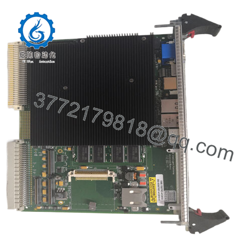
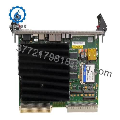
The GE PCI-5565-010 is a PCI Reflective Memory interface board that allows real-time data sharing between up to 256 independent computer nodes over a fiber-optic network. It writes data to onboard SDRAM, and the hardware automatically broadcasts changes to all other nodes with no host processor involvement.
In simulation, data acquisition, and distributed control systems I have commissioned, this board delivers deterministic low-latency transfers that standard Ethernet or fieldbus cannot match. Engineers choose it for the software-transparent operation, high sustained throughput, and ability to connect dissimilar architectures and operating systems in the same ring. It serves as a direct replacement in existing VMIC/GE Reflective Memory networks.

- PCI-5565-010
Installation & Configuration Guide
Stage 1: Pre-Installation Preparation (10-15 minutes) ⚠️ Safety First: Notify operations of scheduled downtime. Verify the host system is in a safe state, perform lock out/tag out on power, and wait 5 minutes for capacitor discharge. Tools Required: Grounded ESD wrist strap, PH1 or PH2 screwdriver, digital multimeter, wire labels, smartphone for photos. Data Backup: Photograph the existing fiber connections and any DIP switch or jumper settings. Record the current node ID, memory base address, and interrupt configuration from your host software or driver.
Stage 2: Removing the Old Module
- Power down the host computer and remove the PCI slot cover.
- Label the transmit (TX) and receive (RX) fiber cables before disconnection. Disconnect fiber-optic cables carefully to avoid dust contamination.
- Release the PCI board retaining screw and gently extract the board from the slot.
- Inspect the PCI slot connectors for bent pins or debris.
⚠️ Keep the old module for reference until the new one operates without issues.
Stage 3: Installing the New Module (10 minutes)
- Wear your ESD strap and work on an ESD-safe surface. Confirm the replacement matches PCI-5565-010 exactly, including fiber mode (multimode or single-mode).
- Configuration Clone (Crucial): Set any onboard switches or jumpers for node ID and memory mapping to match the photographed settings from the old board.
- Align the board with the PCI slot guides and insert it firmly until fully seated. Secure with the retaining screw.
- Reconnect the TX and RX fiber cables exactly as before (TX to next node RX, RX to previous node TX). Clean fiber ends if needed.
Self-Checklist: [ ] Node ID and memory settings match, [ ] Board fully seated and secured, [ ] Fiber cables reconnected in correct order.
Stage 4: Power-On & Testing (15-20 minutes) Pre-Power Check: Use a multimeter to verify no shorts on the PCI power rails. Power-On Steps:
- Power up the host computer with field fiber connections in place but other nodes powered as needed for the ring.
- Boot the system and verify board detection in Device Manager or your diagnostic software.
- Load the Reflective Memory driver and confirm node ID and memory mapping.
- Run built-in loopback or network test routines to verify data propagation across the ring.
- Perform application-level read/write tests to confirm deterministic data sharing.
⚠️ Troubleshooting Note: If the node does not appear on the network, check fiber polarity, cable continuity, and node ID settings. A broken ring (missing or dirty fiber) prevents communication. If data does not propagate, verify redundant mode configuration and interrupt settings.
Frequently Asked Questions (FAQ)
Can this module be hot-swapped under power? No. The PCI-5565-010 does not support hot-swap. Removing or inserting the board with the host powered risks damage to the PCI bus or the module. Always shut down the host computer first.
Is the PCI-5565-010 obsolete, and is the stock genuinely new? Yes, this is a legacy VMIC/GE design now supported under Abaco Systems. Available units are New Original or New Surplus from verified excess or sealed inventory. Each board receives inbound inspection, functional testing on a PCI system with fiber ring simulation, and a test report. Confirm multimode or single-mode variant matches your existing fiber plant.
What serves as a direct replacement if this board is out of stock? Abaco offers the PCI-5565PIORC (PIO version) as an improved drop-in in many cases. Verify PCI bus compatibility, memory size, and fiber type. The original PCI-5565-010 remains the exact match for legacy systems with specific driver or register requirements.
Will I lose my programming or configuration when I replace the board? No. Configuration resides in host software and driver settings. After physical swap and node ID verification, reload or restart the Reflective Memory driver. Existing application code that reads/writes to the shared memory space continues to function.
Why is the price lower than current OEM list pricing? These units come from factory-sealed surplus or authorized excess stock. We do not apply full current-production pricing to legacy Reflective Memory parts. All boards undergo the same rigorous inbound verification, live fiber network testing, and electrical checks.
Does the board support redundant fiber operation? Yes. The 5565 family includes selectable redundant mode that uses a second fiber pair for fault tolerance. Confirm your system configuration and cable plant support this feature if required.
How long is the warranty on this module? We provide a 1-year warranty from shipment date on tested New Surplus or New Original units. This covers functional failures under normal operating conditions. Test videos and photos are available upon request before shipment.


