
 WhatsApp: +86 16626708626
 Email:
 Phone: +86 16626708626
Description
Key Technical Specifications
These are PCIE-5565PIORC family specifications—not confirmation of the supplied -10000 configuration. Do not publish a specific memory capacity, optical type, or environmental rating for this unit without matching documentation.
| Parameter | Value |
|---|---|
| Host Interface | PCI Express x4; compliant with PCI Express Specification Revision 1.1 |
| Compatible Host Slots | Suitable PCIe x4, x8, or x16 slots, subject to host requirements |
| Network Type | Fiber-optic reflective memory network; closed-ring connectivity or supported hub arrangement |
| Optical Serial Rate | 2.12 Gbaud |
| Network Payload Transfer Rate | 43 MB/s with 4-byte packets to 170 MB/s with 64-byte packets; operating mode affects throughput |
| Network Capacity | Up to 256 nodes; unique node IDs from 0 to 255 |
| Onboard Memory | Family options: 128 MB or 256 MB SDRAM with selectable parity; actual unit requires verification |
| Packet Payload | Dynamic packet size: 4–64 bytes |
| Optical Interface | LC fiber connections; separate TX and RX |
| Fiber Distance | Family options: multimode up to 300 m or single-mode up to 10 km between nodes; installed optics determine applicability |
| DMA and Interrupts | One independent DMA channel; four general-purpose network interrupts, each carrying 32 bits of user data |
| Configuration and Firmware | S2 node-ID switch; S1 operating configuration; field-upgradeable firmware |
Family specifications follow the GE hardware reference manual and current reflective-memory product information.
GE’s launch announcement quotes up to 174 MB/s, while the hardware manual and current family page specify up to 170 MB/s. Use 170 MB/s for this family-level listing; do not present either figure as guaranteed application throughput.
Power consumption, operating temperature, dimensions, weight, and installed optical wavelength remain unverified for the exact supplied identifier.
Product Introduction
The GE PCIE-5565PIORC-10000 is identified here as a PCIE-5565PIORC family reflective memory node card, pending exact suffix confirmation. It connects PCIe hosts to a fiber-optic shared-memory network for real-time simulation and distributed test systems.
Writes to local onboard SDRAM automatically propagate to corresponding memory locations on other nodes. Hardware-managed replication avoids host-managed messaging for each transfer. Verify the actual memory capacity, optical option, firmware, and node configuration before ordering a replacement.
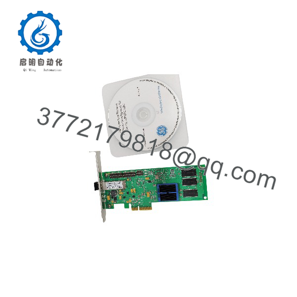
PCIE-5565PIORC-10000
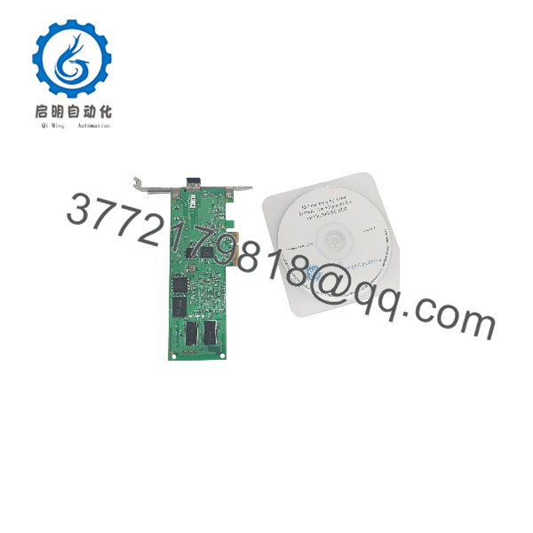
PCIE-5565PIORC-10000
Troubleshooting Quick Reference
| Symptom | Possible Cause | Relevance to this Part | Quick Check Method | Recommendation |
|---|---|---|---|---|
| Card absent from host enumeration | Poor seating, incompatible host configuration, or hardware failure | Hardware fault possible; not established | Check OS PCIe enumeration and driver diagnostics; the manual lists vendor/device IDs 114A/5565 | Verify host compatibility and driver support before replacing |
| Yellow Signal Detect LED remains off | No received light, disconnected fiber, reversed connection, dirty connector, or incompatible optics | Optical path first | Verify upstream TX connects to this card’s RX; inspect/clean connectors using approved fiber procedures; substitute a known-good matching cable | Restore the optical path before condemning the board |
| Signal Detect is on but memory does not update | Incomplete ring, synchronization problem, transfer-mode mismatch, or application mapping error | Network/configuration issue possible | Confirm the complete TX-to-RX ring; compare S1 transfer mode across nodes; read fault/status registers | Light detection alone does not prove valid communication |
| Green Own Data LED stays off during a write test | Local write packets are not returning, or test did not generate qualifying traffic | Ring operation directly relevant | On an isolated bench, write a known pattern to a reserved offset and verify remote receipt and return behavior | Check ring continuity and configuration before replacement |
| Red Status LED is illuminated | User-defined status indication; default power-up state is on | Not a standalone fault indication | Read the application’s LED control logic and board status registers | Do not diagnose hardware failure from this LED alone |
| Data appears at incorrect locations or with wrong byte order | Offset mismatch, memory-window configuration, or endian settings | Application/configuration first | Compare memory maps, access widths, S1 window settings, and endian configuration; use a known pattern | Correct the mapping before replacing hardware |
| Memory updates work but interrupts fail | Wrong destination node, disabled interrupt path, or host driver issue | Interrupt configuration requires isolation | Confirm unique node IDs; inspect LISR, LIER, and INTCSR through supported diagnostics | Separate interrupt delivery from basic memory replication |
| Errors begin after a replacement | Duplicate node ID, inconsistent transfer mode, firmware/driver mismatch, or wrong optical option | Replacement compatibility directly relevant | Compare old/new labels, S1/S2 photographs, reported revisions, optics, and driver versions | Restore verified settings; do not copy unknown defaults |
These checks follow GE’s documented LEDs, ring operation, switch configuration, memory mapping, and interrupt architecture. Run write tests only in a reserved region or isolated test network to avoid altering live process data.
If the problem remains, contact technical support with board-label photos, S1/S2 photos, optical transceiver identification, network topology, OS/driver versions, register diagnostics, and error logs.
Frequently Asked Questions (FAQ)
Is PCIE-5565PIORC-10000 the same as PCIE-5565PIORC-100000?
That equivalence has not been established. The supplied identifier ends in -10000; reviewed references include -100000 and -100A00. Treat the difference as an unresolved ordering-code issue—not a harmless typo.
Require a readable OEM label showing:
- Complete ordering number.
- Serial number.
- Hardware revision.
- Optical option or transceiver identification.
- Installed memory capacity, supported by diagnostics or matching records.
The family supports both 128 MB and 256 MB memory and different optical options. Family membership alone does not identify the supplied unit’s configuration.
Can I replace a PCI-5565PIORC or cPCI-5565PIORC with this card?
Not as a physical drop-in replacement. The PCIE-5565PIORC uses PCI Express; the PCI and cPCI versions use different host interfaces and mechanical formats.
GE documents network operation with other compatible RFM-5565 family members, but network compatibility does not establish host-slot or software interchangeability. Verify the host interface, optics, memory map, driver/API, interrupts, and application requirements separately.
The GE manual permits installation in suitable PCIe x4, x8, or x16 slots. It does not make this a conventional PCI card.
What switch settings must I copy before replacement?
Photograph S1 and S2 before touching the old card, then verify each setting against the manual.
S2 selects the node ID from 0 to 255. Every node must have a unique ID. S1 controls operating options, including redundant transfer mode, memory-window selection, and rogue-master functions. All nodes must use the same redundant/nonredundant transfer mode.
Do not blindly duplicate every switch from an unrelated spare:
- A duplicate node ID violates the network requirement.
- Multiple nodes configured as the same rogue master can remove each other’s marked packets.
- S1 position 8 is reserved for recovery after a failed control-logic flash update; normal operation requires it off after successful recovery.
These are actual hardware configuration risks—not generic PLC address-setting advice.
Will my program, memory contents, and firmware match after a swap?
Do not assume they will. Preserve the host application, driver installer, memory map, initialization sequence, interrupt configuration, and any required application data before removal.
The card uses SDRAM for reflective memory. Treat replacement and power cycling as requiring application-controlled initialization rather than assuming existing shared-memory contents will survive. GE also notes that BIOS-assigned register and memory locations can differ between systems and even between slots.
The family supports field firmware updates, but no firmware revision was supplied for this unit. Record the old card’s reported revisions and confirm the replacement against the installed driver and application. Do not flash firmware simply because a newer file is available.
Can I hot-swap it or use any LC fiber cable?
No hot-swap: GE explicitly prohibits installation or removal while power is applied. Follow the host shutdown procedure and use grounded ESD protection.
An LC connector establishes connector geometry—not optical compatibility. Verify multimode versus single-mode optics, matching cable specifications, and the permitted distance. The family supports multimode links up to 300 m or single-mode links up to 10 km, depending on the installed option.
Connect each TX to the next node’s RX and complete the ring. GE states that the card will not transmit packets if its receiver detects no signal or loses synchronization. Fit dust caps when fibers are disconnected. Never look into an optical port.
For host power, obtain the exact applicable power specification before ordering. Check each required rail and the host’s slot budget; a 20% planning margin does not replace OEM electrical limits.
Is this discontinued, available as new surplus, or covered by a warranty?
The exact ordering code’s lifecycle, stock, condition, lead time, and warranty remain unverified.
Do not transfer another product’s lifecycle notice to this card. For example, Abaco’s Restricted Production Phase notice for the older PCI-5565 concerns that specific product, not proof of the PCIE-5565PIORC-10000’s status.
Require a written quote identifying the exact unit, quantity, dispatch date, condition, included bracket/accessories, and warranty terms. “New Original / New Surplus” requires evidence of unused OEM stock. “Refurbished (tested)” requires documented work and test results. “Factory Sealed” must describe an intact original seal—not resealed seller packaging.
A lower price establishes neither authenticity nor technical equivalence. Do not publish authorized-stock or OEM-warranty claims without supporting documentation.
What inspection and testing should the supplier document?
Request a serial-linked acceptance report in this order. No actual-unit test results were supplied.
- Inbound inspection and traceability
Review available OEM packing lists, purchase records, and applicable customs documents. Resolve the complete ordering number before acceptance. Inspect for corrosion, scratches, rework, discoloration, damaged components, bracket deformation, and contaminated or damaged optics. Audit manuals, certificates, and accessories. Check security markings only where that production version used them. - Live functional testing
Identify the PCIe test host, OS, driver version, compatible peer card or hub, fiber type, and instrument details. Record host detection, reported memory capacity, revisions, and LED behavior. Test local memory access, bidirectional remote pattern replication, supported DMA, and required interrupts using an isolated network. For a run exceeding 24 hours, log traffic pattern, duration, errors, ambient conditions, and thermal observations. An Ethernet ping does not test reflective-memory operation. - Electrical parameter testing
Perform appropriate documented low-voltage checks and installation-grounding verification. Do not apply a generic 500 V megohmmeter test across PCIe contacts or board circuitry. No reviewed source establishes that as an approved acceptance procedure. Require an applicable OEM method before insulation-resistance or hipot testing. - Firmware and configuration verification
Record hardware and firmware information, driver version, S1/S2 positions, memory-window settings, endian configuration, and interrupt routing. Confirm unique node ID and common transfer mode. Preserve photographs and diagnostic exports with the serial-linked report. - Final QC and packaging
Require inspector sign-off, a dated report and QC label, protective optical caps, ESD shielding packaging, cushioning, and a rigid corrugated box. Request actual-unit test photos and videos where available. Claim “verified functional under documented test conditions” only when those records exist.



