
 WhatsApp: +86 16626708626
 Email:
  Phone: +86 16626708626
Description
Key Technical Specifications
| Parameter | Specification Value |
| Processor Type | Intel Core 2 Duo L7400 |
| Clock Speed | 1.5 GHz |
| System Memory | 2 GB DDR2 SDRAM (dual-channel, soldered) |
| Onboard Flash Memory | 4 GB CompactFlash card |
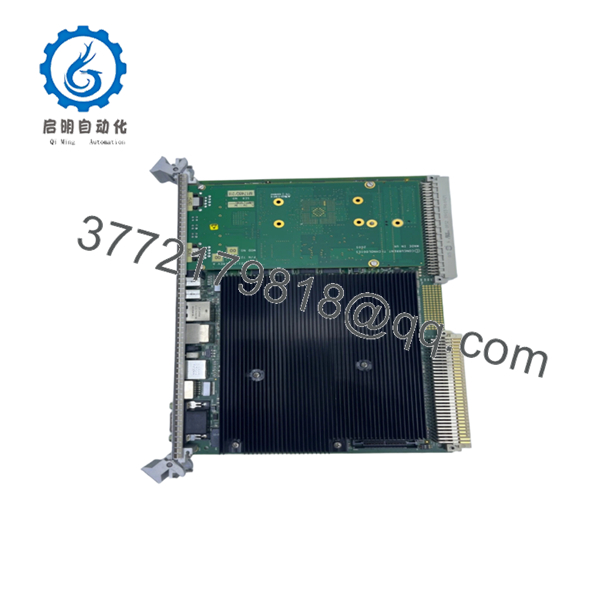
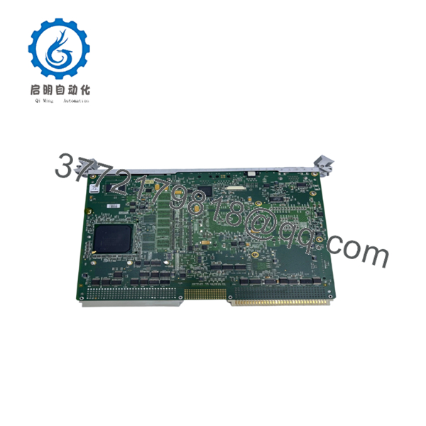
| Form Factor | 6U VMEbus |
| VMEbus Interface | Universe II bridge chip (supports VME64) |
| Ethernet Interfaces | 2 x 10/100/1000Base-T Gigabit ports (front panel) |
| Serial Interfacing | 2 x RS-232/422/485 ports via RJ45 connectors |
| USB Connectivity | 2 x USB 2.0 ports (front panel) |
| Video Output | 1 x analog VGA port |
| Operating Temperature | 0 to +55 °C (standard commercial grade) |
| Power Requirements | +5 V (approx. 4.5 A), +12 V (approx. 0.1 A) |
Product Introduction & Supply Chain Strategy
The GE VME-7807RC-412000-350-93007807-412000G is a high-performance 6U VME Single Board Computer based on the Intel Core 2 Duo processor. Engineered for deterministic, embedded control loops, this board handles intense real-time computational payloads in aerospace simulation, defense radars, maritime automation, and heavy industrial process lines. It serves as the master processing node within a VMEbus rack, bridging modern high-speed I/O interfaces with legacy fieldbus backplanes.
From a lifecycle and inventory management perspective, securing this exact hardware configuration as New Surplus is a critical risk-mitigation strategy. Because this architecture is completely discontinued by the OEM, asset managers face severe exposure to multi-day stock-out incidents. Choosing New Surplus over refurbished components eliminates the Total Cost of Ownership (TCO) penalties driven by degraded solder joints or latent capacitor wear. Maintaining at least one verified, unpowered buffer stock unit on-site protects your system against catastrophic processing failures without forcing an expensive, multi-million dollar system migration.

- VME-7807RC-412000-350-93007807-412000G
- VME-7807RC-412000-350-93007807-412000G
Installation & Configuration Guide
Stage 1: Pre-Installation (Prep & Safety)
- Isolate power to the VME chassis. Execute standard lock-out/tag-out (LOTO) safety procedures.
- Put on a grounded, static-dissipative ESD wrist strap connected directly to the bare-metal frame of the chassis.
- Before pulling the legacy unit, document the exact software configuration and record any existing cable routing labels.
- Unpack the new module within an ESD-safe zone, verifying the backplane pins are straight.
Stage 2: Removal
- Loosen the front-panel retaining screws on the top and bottom ejector handles of the failed card.
- Unplug all front-panel connections, including Ethernet, VGA, and serial cables.
- Press the top and bottom ejector handles outward simultaneously to disengage the board’s connectors from the VMEbus backplane.
- Slide the card out along the guide rails, handling it only by the front panel and card edges. Place it immediately into an ESD bag.
Stage 3: Installation (Clone & Seat)
- Inspect the PMC/XMC expansion slots or onboard configuration headers. Ensure they match your previous hardware setup.
- Align the new board with the card guides in the designated slot (typically Slot 1 if it acts as the VME system controller).
- Push the module smoothly along the rails until the ejector handles meet the chassis frame.
- Pivot the handles inward simultaneously until the card seats firmly into the backplane connectors. Hand-tighten the retention screws.
Stage 4: Power-On & Testing
- Reconnect all communication, network, and video cables to the front panel ports.
- Clear the LOTO tags and restore power to the VME chassis.
- Observe the front panel LED cluster during the boot sequence. The red ERR/FAIL LED must turn off after the power-on self-test (POST) completes, leaving the green RUN/SYS LED illuminated.
- Verify system operation via the serial console or connected terminal to ensure the operating system boots cleanly and recognizes the VME backplane target cards.
Firmware/Software Versions & Upgrade Notes
Operating this single board computer requires aligning the system BIOS and VME bridge firmware with your real-time operating system (RTOS) platform, whether running VxWorks, Linux, or Windows Embedded.
⚠️ CRITICAL INTEGRATION WARNING: The embedded Universe II VME bridge relies on specific register initialization scripts mapped to your operating system’s Board Support Package (BSP). Swapping hardware with mismatched BIOS revisions can cause immediate PCI-to-VME bus errors or interrupt timeouts.
Always document your existing system’s firmware baseline before running a hot swap. Moving from older stepping revisions to this specific “G” suffix module can alter backplane timing tolerances slightly. Avoid updating firmware or flash boot sectors during an emergency troubleshooting event; get the system stable on a verified baseline version first to isolate hardware performance from configuration variables.
Frequently Asked Questions (FAQ)
Why is this New Surplus module more expensive than refurbished alternatives?
Our pricing directly reflects the strict quality verification and reliability metrics associated with authentic, unissued inventory. While refurbished parts are cleaned, superficially tested, and sold with worn components, this unit features zero structural wear, un-degraded capacitors, and flawless backplane pins. Spending slightly more up-front prevents an un-planned outage that can quickly cost ten times the initial purchase price of the module.
Is this specific VME-7807RC hardware still actively supported by the OEM?
No. This single board computer family is obsolete and has passed its official End-of-Life (EOL) cycle. The original manufacturer no longer builds these units or provides standard direct repair support. Because of this obsolescence, maintaining an on-site, pre-tested buffer stock is the only reliable way to guarantee plant availability during a processor failure.
Can I hot-swap this processing board while the VME chassis is powered up?
Absolutely not. The 6U VMEbus architecture used on this board does not support live, unbuffered hot-swapping. Pulling or inserting this module into a powered backplane will cause electrical arcing across the data and power pins, which risks permanently destroying the Universe II bus controller and damaging adjacent I/O modules on the rack. Always isolate the chassis power source completely before extraction.
Does this unit retain its operating system and runtime logic when powered down?
Yes. The onboard 4 GB CompactFlash card acts as non-volatile, solid-state storage that retains your operating system, application binaries, and static configuration files during total power loss. However, volatile variables stored in the 2 GB DDR2 SDRAM are cleared upon power-down, meaning your system master must reload its execution states upon a clean reboot.
What kind of warranty covers this New Surplus hardware?
We back this module with a comprehensive 1-year operational warranty, ensuring that it meets all original OEM functional parameters out of the box. Every unit is stored in climate-controlled facilities, undergoes strict ESD-safe inbound testing, and ships in heavy-duty packaging with fully verifiable serial numbers.


