
 WhatsApp: +86 16626708626
 Email:
  Phone: +86 16626708626
Description
3. Key Technical Specifications
| Parameter | Value |
|---|---|
| Channels | 32 optically isolated outputs |
| Output Current (per channel) | 2.5 to 300 mA (programmable) |
| Output Voltage Range | 2.5 to 30 VDC (normal mode) |
| Isolation (Channel-to-Channel) | 1,000 VDC continuous / 6,000 VDC pulse |
| Isolation (Channel-to-VMEbus) | 1,000 VDC continuous / 6,000 VDC pulse |
| Optocoupler Type | High-speed optocoupler |
| Output Register | Four 8-bit output registers (32-bit total) |
| Data Transmission | 8-bit and 16-bit supported |
| Access Level | Monitoring and non-privileged data transmission |
| Pull-up Resistors | Field-configurable (source or sink mode) |
| Form Factor | Dual-slot 6U VME (dual Eurocard) |
| Dimensions (H×D×W) | 9.2 in × 6.3 in × 0.8 in (234 × 160 × 20 mm) |
| Operating Temperature | 0 to +55°C |
| Storage Temperature | -20 to +85°C |
| Noise Immunity | High noise resistance, optimized for VMEbus |
| Weight | ~0.5 kg |
| Surge Protection | Field-configurable pull-up for transient protection |
4. Product Introduction
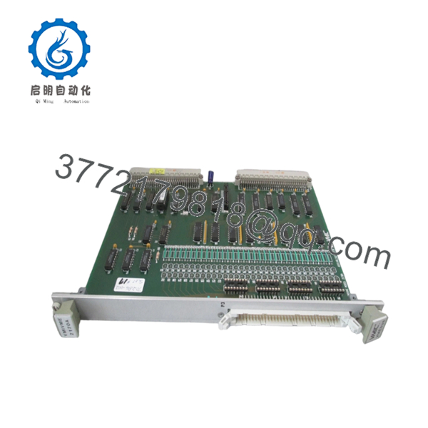
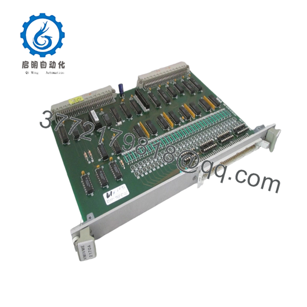
The GE VMIC 333-102170-000 is a 32-channel optically isolated high-level digital output board for VMEbus-based industrial control systems. It is designed for safe transmission of digital control signals to field devices such as relays, solenoids, and indicator lamps in electrically noisy environments.
This module stands out for its flexible output current range (2.5-300 mA per channel), field-configurable pull-up resistors supporting both source and sink modes, and high isolation (1,000 VDC continuous, 6,000 VDC pulse), which protects the VMEbus backplane from field-side transients and ground loops. The dual-slot 6U form factor with four 8-bit output registers provides robust control for multi-voltage systems requiring galvanic isolation
5. Troubleshooting Quick Reference
| Symptom | Possible Cause | Relevance to this Part | Quick Check Method | Recommendation |
|---|---|---|---|---|
| No LEDs on power-up | VMEbus power failure or backplane fault | ❌ Low | Measure +5V, +12V at backplane connector with Fluke multimeter | Check PSU and crate power before replacing; verify board is seated in correct dual-slot pair |
| Module not detected by CPU | Slot address misconfiguration or VMEbus timeout | ⚠️ High | Read VMEbus controller diagnostic buffer; check board presence register | Match slot address to system config (DIP switches); reseat module firmly |
| Some outputs dead (no voltage on load) | Output driver damage or optocoupler failure | ⚠️ High | Inject known-good VMEbus command; measure output voltage at terminals with multimeter | Isolate bad channels; if >3 fail, replace entire board |
| All outputs fail but board detected | Pull-up voltage missing or configuration error | ⚠️ High | Measure pull-up voltage at field connector; verify DIP switch configuration | Apply correct pull-up voltage (2.5-30V); check source/sink mode matches load |
| Random output toggling | Field wiring noise or grounding loop | ⚠️ High | Oscilloscope on output terminals; check for voltage spikes >30V | Add shielded cable; verify single-point grounding; install surge suppression if needed |
| ERR light flashing | Internal memory or register fault | ✅ High | Read diagnostic buffer via system software | Usually requires hardware replacement; test report available |
| Outputs stuck ON (can’t turn off) | Optocoupler latch-up or driver short | ✅ High | Measure output voltage with command OFF; disconnect load and retest | Replace board immediately; check for overvoltage on field side |
Note: If diagnostics are inconclusive, contact technical support with photos of the module, diagnostic buffer logs, wiring diagrams, and multimeter readings. Test videos available upon request.

- VMIC 333-102170-000
- VMIC 333-102170-000
6. Frequently Asked Questions (FAQ)
Q: Is this VMIVME-2170A still being manufactured by GE?
A: No, this is an obsolete model. GE Fanuc automation operations were absorbed into broader GE Electrification, and VMIC VMEbus boards are no longer in active production. What we stock is New Surplus (never used, original packaging) or Professionally Refurbished units (tested per SOP below). Lead times depend on available inventory.
Q: What’s the difference between the -2170A and earlier versions like -2170?
A: The “A” suffix indicates an improved revision with better optocoupler isolation and tighter current tolerance. The -2170A provides 1,000 VDC continuous isolation versus 500 VDC on the original -2170, and has improved thermal performance. Before pulling your old board, document the exact suffix from the label. Request the same revision when ordering to avoid compatibility issues with your existing power supply.
Q: Can I hot-swap this module in a running VMEbackplane?
A: No, it’s not hot-swappable. The VMEbus specification for this board does not support hot-plug. Power down the crate before inserting or removing the module. Doing otherwise can fry the backplane or the board itself, especially since the optocouplers can latch up on hot-plug transients. I’ve seen a $1,200 board let the magic smoke out because someone tried a “quick swap” without powering down. Kill the power first.
Q: How do I configure source vs. sink mode for the outputs?
A: Source/sink mode is set via field-configurable pull-up resistors at the terminal block, not DIP switches on the board. Wire the pull-up to +V (source mode) or GND (sink mode) depending on your load type. Take a clear photo of your old module’s wiring before removal. Mirror that exact configuration on the new unit. It’s the most common rookie mistake—getting the polarity wrong and wondering why the solenoid won’t energize. Seriously, photograph before you touch.
Q: What’s the maximum load I can drive per channel, and can I parallel channels?
A: Each channel can handle up to 300 mA at 2.5-30 VDC. Do not parallel channels to drive higher currents—the optocouplers won’t share current evenly, and one will fail first, potentially taking out the whole board. If you need to drive a 500 mA load, use an external relay driver or transistor buffer. I’ve watched a tech parallel two channels to drive a valve coil, and within a week one channel failed, taking the whole system down. Use an external driver.
Q: Does this come with a warranty, and what does it cover?
A: Yes, all units come with a 1-Year Warranty covering functional failures under normal operating conditions. It does not cover damage from improper installation, overvoltage beyond 30V, ESD mishandling, or exceeding 300 mA per channel. We test every board before shipping (see SOP below), and test reports with channel-by-channel output verification are available upon request.
Q: Why is this cheaper than buying from the OEM factory?
A: Because the OEM no longer manufactures it. You’re buying surplus stock from closed production lines or refurbished units from decommissioned plants. The price reflects the obsolete status, not compromised quality. Every unit goes through our full inspection and live testing SOP—photos and test videos are available if you ask. Each channel is tested with load simulation to verify 300 mA capability.
Q: Will this work with my existing VMEbus controller from a different manufacturer?
A: Yes, as long as your controller follows the ANSI/VITA 1 VMEbus standard and supports dual-slot 6U boards. The VMIVME-2170A is a standard dual Eurocard board with monitoring and non-privileged access. However, verify your backplane supports the power draw (~15 W at full load) and that your software has drivers for VMIC boards. Check your rack’s current budget before installing.
Q: What’s the maximum pull-up voltage I can apply, and what happens if I exceed it?
A: The maximum pull-up voltage is 30 VDC. Exceeding 30V can damage the optocouplers internally, and the damage may not be visible on visual inspection. The board will appear to work initially but fail prematurely under load. Always verify your field power supply with a multimeter before connecting. I once watched a tech connect 48V to a 24V system, and the board worked for 3 days before the optocouplers started failing one by one. Don’t wire from memory—check the manual.
Q: Can I use this board to control AC loads directly?
A: No, this board is designed for DC loads only (2.5-30 VDC). The optocouplers are not rated for AC, and attempting to switch AC directly will damage the output drivers. For AC loads (120VAC, 240VAC), use an external relay or solid-state relay (SSR) with the VMIVME-2170A driving the relay coil. The isolation provided by the board protects the VMEbus from the AC side. Never wire AC directly to this board.


