
 WhatsApp: +86 16626708626
 Email:
  Phone: +86 16626708626
Description
3. Key Technical Specifications
| Parameter | Value |
|---|---|
| Channels | 4 synchronous (S/D) or resolver (R/D) converters |
| Resolution | Software-programmable: 10, 12, 14, or 16 bits |
| Tracking Rate (Resolver) | Up to 800 rps (48,000 RPM) |
| Tracking Rate (Synchronous) | Up to 160 rps |
| Accuracy | ±2.3 arc-min (±0.038°), option: ±2 arc-min +1 LSB |
| Differential Linearity | ±4 LSB (maximum) |
| Bandwidth | Software-programmable: 530 Hz or 130 Hz |
| Reference Frequency | 360 Hz (low bandwidth) to 6 kHz (for resolver) |
| Reference Voltage Input | 4 to 130 VRMS |
| Reference Input Impedance | 110 kΩ nominal (100 kΩ minimum), single-ended |
| Pitch Counter | 16-bit per channel |
| Data Transfer | 8-bit, 16-bit, or 32-bit |
| Register Access | S/R data (16-bit) + pitch counter (16-bit) as 32-bit double word |
| VMEbus Access | Short I/O (non-privileged) and Supervisory Short I/O (selectable via DIP) |
| Board Address | 11-bit DIP switch (A05-A15); A00-A04 for register selection |
| Built-In Test | Yes (resolver option only; requires P2 connector input signal) |
| LEDs | Signal presence, error >65 LSB, board fault, signal loss |
| Form Factor | Dual-slot 6U VME (dual Eurocard) |
| Dimensions (H×D) | 9.2 in × 6.3 in (234 × 160 mm) |
| Operating Temperature | 0 to +55°C |
| Storage Temperature | -20 to +85°C |
| Relative Humidity | 20% to 80%, non-condensing |
| Power Supply | +5V @ 2 A, ±15V @ 100 mA (VMEbus backplane) |
| Power Consumption | ~15-20 W |
| Weight | ~0.5 kg |
4. Product Introduction
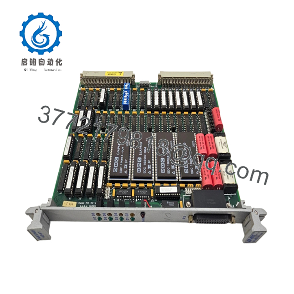
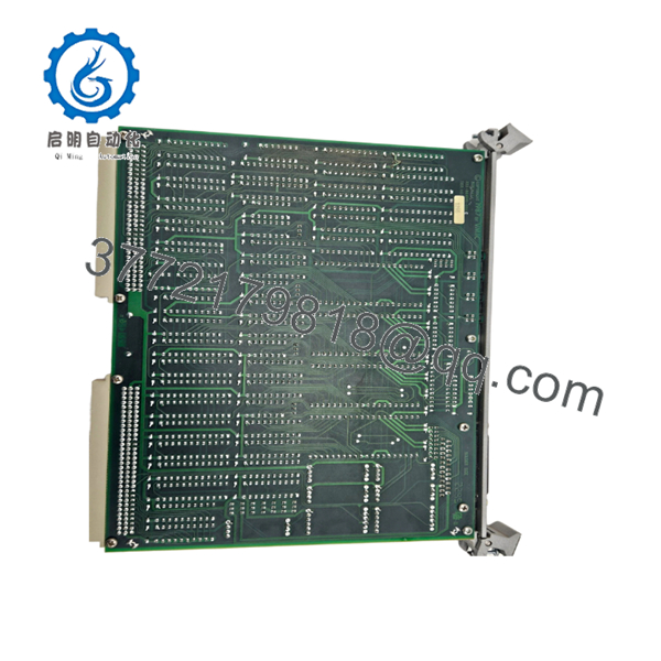
The GE VMIC VMIVME-4941-444 is a 4-channel resolver/synchronous-to-digital converter (R/D and S/D) board for VMEbus-based motor control, robotics, CNC, and process control systems. It provides precise position and velocity feedback from resolvers or synchronous transducers with programmable resolution (10-16 bits) and high tracking rates up to 800 rps (48,000 RPM).
This module stands out for its software-programmable resolution and bandwidth, which allow you to balance tracking speed against accuracy for different applications. The ±2.3 arc-min accuracy, 16-bit pitch counter per channel, and built-in test capability make it suitable for high-performance motor control, radar antenna positioning, robotic axis control, and machine tool applications where precise angular position feedback is critical.

- VMIVME-4941-444
- VMIVME-4941-444
5. Troubleshooting Quick Reference
| Symptom | Possible Cause | Relevance to this Part | Quick Check Method | Recommendation |
|---|---|---|---|---|
| No LEDs on power-up | VMEbus backplane power failure or incorrect slot | ❌ Low | Measure +5V, +15V at backplane connector with Fluke multimeter | Check PSU and crate power before replacing; verify board is seated in correct dual-slot pair |
| Board not detected by CPU | Slot address DIP switch misconfiguration or VMEbus timeout | ⚠️ High | Check VMEbus controller diagnostic buffer; verify board presence register | Match DIP switch address (A05-A15) to system config; reseat module firmly |
| Fault LED stays on after power-on | Resolver/synchronous input signal missing or error >65 LSB | ⚠️ High | Measure reference voltage at input (4-130 VRMS); check signal presence LED | Verify resolver/synchronous wiring; check reference frequency (360 Hz-6 kHz); confirm signal not lost |
| All 4 channels read incorrectly | Reference voltage missing or resolver test mode active | ⚠️ High | Measure reference at P2 connector; verify jumper settings for direct input mode | Confirm reference voltage 4-130 VRMS; if using built-in test, expect 20 LSB accuracy limit |
| Single channel reads erroneous position | Resolver winding damage or channel conditioning fault | ⚠️ High | Inject known resolver test signal to suspect channel; compare with adjacent channels | Isolate bad channel; check resolver winding resistance; if >2 channels fail, replace entire board |
| Position jumps or tracks poorly | Bandwidth too low or resolver gain mismatch | ⚠️ Medium | Check software bandwidth setting (530 Hz vs 130 Hz); verify resolver gain trim | Increase bandwidth to 530 Hz for high-speed; adjust resolver gain per OEM manual |
| High error count (>65 LSB) | Resolver wiring error or phase mismatch | ⚠️ High | Measure resolver S1/S2/S3/S4 windings; check phase with oscilloscope | Verify resolver pinout; confirm S1/S3 and S2/S4 pairs; check for shorted/open windings |
Note: If diagnostics are inconclusive, contact technical support with photos of the board, diagnostic logs, resolver wiring diagrams, and multimeter/oscilloscope readings. Test videos with channel-by-channel verification available upon request.
6. Frequently Asked Questions (FAQ)
Q: Is this VMIVME-4941-444 still being manufactured by GE?
A: No, this is an obsolete model. GE Fanuc automation operations were absorbed into GE Electrification, and VMIC VMEbus R/D converter boards are no longer in active production. What we stock is New Surplus (never used, original packaging) or Professionally Refurbished units tested per SOP. Lead times depend on available inventory.
Q: What’s the difference between resolver (R/D) and synchronous (S/D) mode?
A: Resolver mode accepts AC excitation resolvers (typical for industrial motors, 360 Hz-6 kHz reference, 4-130 VRMS), while synchronous mode accepts digital sine/cosine signals (index/encoder). The VMIVME-4941-444 supports both, but you must configure the correct mode in software and wire the input accordingly. If you’re replacing a board for motor control, you almost certainly need resolver mode. Don’t mix them up—if you wire a resolver to synchronous inputs, you’ll get garbage position data.
Q: Can I hot-swap this module in a running VME crate?
A: No, it’s not hot-swappable. The VMEbus specification for this board does not support hot-plug. Power down the crate before inserting or removing the module. Hot-plug can damage the resolver input amplifiers and reference circuitry. I’ve seen a board fail immediately after hot-plug because the resolver input latched up. Use a grounded wrist strap, and kill the power first.
Q: How do I set the board address, and what happens if it conflicts with another board?
A: The board address is set via 11-bit DIP switches (A05-A15). A00-A04 are used for register selection internally. Document your old board’s DIP switch settings before removal. Mirror that exact configuration on the new unit. If two boards have the same address, the VMEbus controller will timeout or read garbage data. It’s the most common rookie mistake—getting the address wrong and wondering why the motor won’t home. Take a clear photo before you touch anything. Seriously.
Q: What resolution should I use: 10, 12, 14, or 16 bits?
A: It depends on your application speed vs. accuracy trade-off. 10-bit gives the highest tracking rate (good for fast motors), while 16-bit gives the highest accuracy (±2.3 arc-min) but lower tracking bandwidth. For motor control >10,000 RPM, use 10-12 bits. For robotics/CNC positioning, use 14-16 bits. Don’t max out resolution if your motor runs fast—you’ll lose tracking and get position errors. Match resolution to your speed requirements.
Q: Does this come with resolver test capability, and what’s needed for it?
A: Yes, the resolver option has built-in test capability, but it requires you to provide a resolver input signal at the P2 VMEbus extension connector for loopback testing. Built-in test accuracy is limited to ~20 LSB (less precise than normal operation). All four channels use the internal DC reference of channel-zero resolver module during test. If you need full functional testing, use an external resolver simulator. Don’t assume built-in test is production-ready—it’s for diagnostics only.
Q: What’s the warranty, and what does it cover?
A: All units come with a 1-Year Warranty covering functional failures under normal operating conditions. It does not cover damage from overvoltage, resolver wiring shorts, ESD mishandling, or improper gain/bandwidth configuration. Every board is tested on an in-house VME test rack with all 4 channels verified at multiple resolutions. Test reports with channel-by-channel accuracy data are available upon request.
Q: Why is this cheaper than buying from the OEM factory?
A: Because the OEM no longer manufactures it. You’re buying surplus stock from closed production lines or decommissioned systems. The price reflects obsolete status, not compromised quality. Every unit undergoes our full inspection SOP: inbound traceability, live VMEbus functional testing, all 4 channels tested with resolver/synchronous input simulation, electrical parameter verification, and ESD-safe packaging. Test videos are available if you ask.
Q: Will this work with my resolver from a different motor manufacturer?
A: Yes, as long as the resolver matches the input specifications: 360 Hz to 6 kHz reference frequency, 4-130 VRMS excitation, and standard S1/S2/S3/S4 winding configuration. The VMIVME-4941-444 is not resolver-brand-specific; it’s a generic R/D converter. However, verify your resolver’s turns ratio and gain settings match the board’s input range. Don’t wire from memory—check your resolver datasheet for pinout and excitation requirements.
Q: The error LED shows >65 LSB, but the motor still runs. Should I worry?
A: Yes, error >65 LSB indicates the resolver tracking error has exceeded the threshold, which means the board can’t accurately track the resolver position. This could cause motor instability, position drift, or eventual loss of synchronization. Check resolver wiring first (loose connections, phase mismatch), then verify reference voltage (4-130 VRMS), and adjust resolver gain trim. If the motor runs erratically, shut it down immediately and troubleshoot. Don’t ignore error LEDs—in my experience, >65 LSB errors usually lead to motor runaway within minutes.


