
 WhatsApp: +86 16626708626
 Email:
  Phone: +86 16626708626
Description
Key Technical Specifications
- Form Factor: VME 6U single slot
- Input Channels: 64 optically coupled digital inputs
- Input Voltage Range: 5 to 125 VDC (voltage sensing or contact sensing)
- Isolation: 1 kV sustained, 3.5 kV pulsed (field to VMEbus)
- Data Transfers: 8-bit, 16-bit, 32-bit compatible
- Addressing: Standard VMEbus A16 or A24 with DIP switch selection
- Built-in Test: Yes, supports input verification
- I/O Interface: Front panel connectors
- Polarity: Positive or negative true logic options
- Operating Temperature: 0°C to 60°C (standard for series)
- Power Requirements: Draws from VMEbus backplane (+5V typical)
- Connectors: Dual or multi front panel for field wiring
Product Introduction
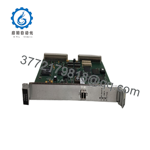
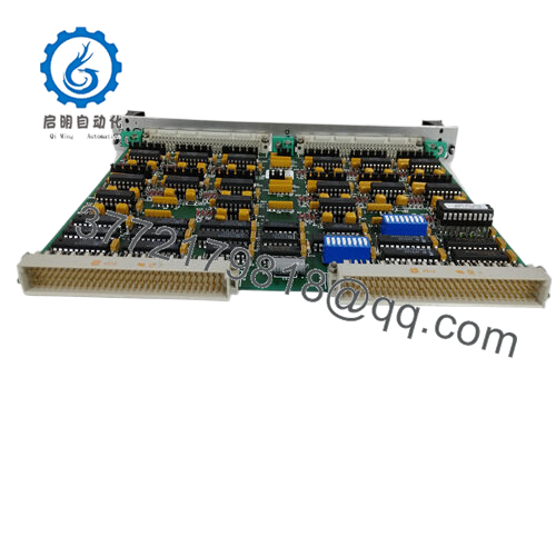
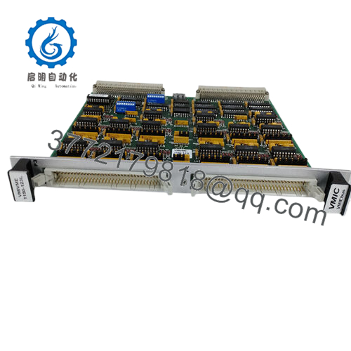
The GE VMIVME-1150-102 with part number 332-001150-102 is a 6U VMEbus 64-bit optically coupled digital input board. It reads 64 field digital signals with optical isolation that protects the VMEbus backplane from transients and ground loops.
In VME systems I have commissioned over the years, this board handles high-density isolated inputs reliably in control and monitoring applications. Engineers select it for the 1 kV isolation rating, flexible input voltage range, and straightforward register-based access via standard VME data transfers. It serves as a direct replacement in legacy VMIC/GE VME racks that need expanded isolated digital input capacity without redesign.

- VMIVME-1150-102 (332-001150-102)
Installation & Configuration Guide
Stage 1: Pre-Installation Preparation (10-15 minutes) ⚠️ Safety First: Notify operations of scheduled downtime. Verify the system is in a safe state, perform lock out/tag out on power supplies, and wait 5 minutes for capacitor discharge. Tools Required: Grounded ESD wrist strap, PH1 or PH2 screwdriver, digital multimeter, wire labels, smartphone for photos. Data Backup: Photograph the front panel wiring layout, record DIP switch settings for base address and mode, and note any interrupt or polarity configurations in your VME controller software.
Stage 2: Removing the Old Module
- Remove the front bezel or cover if present.
- Label wire groups before disconnection. Disconnect field wiring from the front panel connectors carefully.
- Release the VME locking tabs or ejector handles and pull the board straight out to protect backplane pins.
- Inspect the backplane connectors for bent pins, corrosion, or dust.
⚠️ Keep the old module for reference until the new one runs without issues.
Stage 3: Installing the New Module (10 minutes)
- Wear your ESD strap and work on an ESD-safe surface. Confirm the replacement matches VMIVME-1150-102 (332-001150-102) exactly.
- Configuration Clone (Crucial): Set the DIP switches on the new board to match the photographed settings from the old unit. Focus on base address selection.
- Align the board with the slot guides and insert it firmly into the VME rack until fully seated. Secure the front panel screws or tabs.
- Reattach field wiring using your labels and apply proper torque to connectors.
Self-Checklist: [ ] DIP switches match exactly, [ ] Board fully seated and locked, [ ] All wiring reconnected and verified.
Stage 4: Power-On & Testing (15-20 minutes) Pre-Power Check: Use a multimeter to confirm no shorts on the VME power rails. Power-On Steps:
- Apply power to the VME rack only (keep field devices disconnected initially).
- Observe board detection through the host controller.
- Run built-in test routines to verify all 64 input channels.
- Reconnect field signals and perform a dry-run test by monitoring input status registers.
- Confirm correct logic polarity and no false readings.
⚠️ Troubleshooting Note: If inputs do not register correctly, recheck the DIP switch base address and data transfer mode. Communication or detection failures often stem from mismatched addressing or incomplete backplane seating. Verify field signal voltages fall within the 5-125 VDC range.
Frequently Asked Questions (FAQ)
Can this module be hot-swapped under power? No. The VMIVME-1150-102 does not support hot-swap. Removing or inserting the board with power applied risks damage to the VME backplane or the module. Always remove rack power first.
Is the VMIVME-1150-102 obsolete, and is the stock genuinely new? Yes, this is a legacy VMIC/GE Fanuc design now under Abaco Systems. Units listed as New Original or New Surplus come from verified excess or sealed inventory with traceability. Each board undergoes inbound inspection, functional testing on a VME rack, and generation of a test report. Confirm the exact revision matches your system before ordering.
What serves as a direct replacement if this board is out of stock? Abaco Systems may offer updated equivalents in the VME-1150 family. Check pin-for-pin compatibility, isolation ratings, and software register map. Many existing VME racks continue to use the VMIVME-1150-102 (332-001150-102) for exact form, fit, and function.
Will I lose my programming or configuration when I replace the input board? No. The VMIVME-1150-102 is a read-only input peripheral. Your application logic and addressing reside in the VME processor or controller software. After physical installation and address verification, the existing program should read the inputs without changes.
Why is the price lower than current OEM list pricing? These units are new surplus from factory-sealed or authorized excess stock. We do not apply full current-production pricing to legacy parts. All boards receive the same rigorous inbound verification, live functional testing of input channels, and electrical checks.
Does the board support contact sensing on the inputs? Yes. The 64 inputs accept either voltage sensing (5-125 VDC) or dry contact sensing, depending on field wiring. Refer to the hardware reference manual for exact threshold and debounce details if needed.
How long is the warranty on this module? We provide a 1-year warranty from shipment date on tested New Surplus or New Original units. This covers functional failures under normal operating conditions. Test videos and photos are available upon request before shipment.


