
 WhatsApp: +86 16626708626
 Email:
  Phone: +86 16626708626
Description
Key Technical Specifications
- Form Factor: VME 6U single slot
- Relay Channels: 32 independent relays
- Relay Type: Form A (SPST), optional mercury-wetted contacts
- Contact Rating: 50 VA maximum per relay
- I/O Interface: Two front panel 32-pin connectors
- Data Transfers: 8-bit, 16-bit, 32-bit compatible
- Addressing: Standard VMEbus (A16 or A24) with DIP switch configuration
- Polarity Options: Positive or negative true logic (data inversion via board selection)
- Built-in Features: Relay coil status monitoring support in some configurations
- Operating Temperature: 0°C to 60°C (standard for series)
- Power Requirements: Draws from VMEbus backplane (+5V typical)
- Connectors: Dual 32-pin front panel for field wiring
Product Introduction
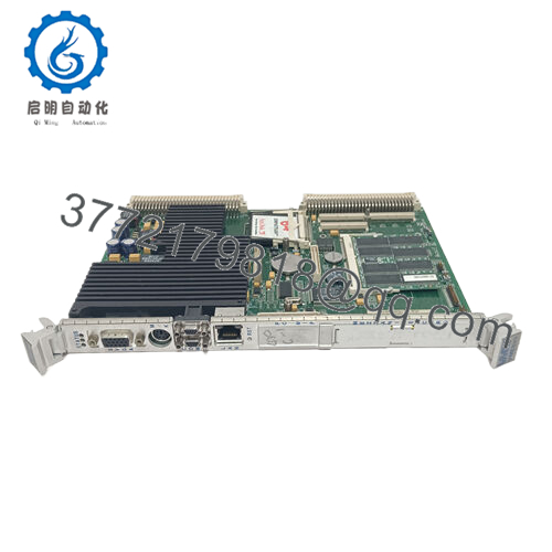
The GE VMIVME-2200 is a VMEbus-compatible 32-channel relay output board designed for industrial control applications. It provides 32 independent Form A (SPST) relays for switching field loads directly from the VMEbus backplane.
In VME systems I have commissioned, this board delivers reliable isolated switching where higher current or voltage handling is needed beyond solid-state outputs. Engineers select it for the straightforward relay interface, dual front-panel connectors that simplify field wiring, and compatibility with existing VMIC/GE VME racks. It works well in applications requiring dry contact outputs or where galvanic isolation from the bus improves noise immunity.
Installation & Configuration Guide
Stage 1: Pre-Installation Preparation (10-15 minutes) ⚠️ Safety First: Notify operations of planned downtime. Place the system in a safe state, perform lock out/tag out on all power sources, and wait 5 minutes for any stored charge to dissipate. Tools Required: Grounded ESD wrist strap, PH1 or PH2 screwdriver, digital multimeter, wire labels, smartphone for documentation. Data Backup: Photograph the existing board’s front panel wiring, record the DIP switch settings for base address, and note any polarity or mode configurations in your VME controller software.
Stage 2: Removing the Old Module
- Remove the front panel cover or bezel if installed.
- Label each wire group before disconnection. Disconnect field wiring from the two 32-pin connectors without forcing pins.
- Release the VME ejector handles or locking tabs and extract the board straight out to avoid damaging backplane connectors.
- Inspect the VME backplane pins for any bending, oxidation, or debris.
⚠️ Keep the removed module available for reference until the replacement operates correctly.
Stage 3: Installing the New Module (10 minutes)
- Wear your ESD strap and work on a protected surface. Verify the new board matches the exact VMIVME-2200 model and revision.
- Configuration Clone (Crucial): Set the DIP switches on the new board to match the photographed settings from the old unit. Pay close attention to the base address selection.
- Align the board with the slot guides and insert it fully into the VME rack until the connectors seat properly. Secure the front panel screws or tabs.
- Reconnect the field wiring to the two 32-pin connectors using your labels and apply correct torque.
Self-Checklist: [ ] DIP switches match exactly, [ ] Board fully seated and secured, [ ] All wiring reconnected and checked.
Stage 4: Power-On & Testing (15-20 minutes) Pre-Power Check: Measure for shorts across the VME power rails with a multimeter. Power-On Steps:
- Energize the VME rack only (keep field loads disconnected initially).
- Monitor board operation through the host controller or diagnostic software.
- Write test patterns to the relay registers and verify each relay activates (listen for click or measure continuity at the output connectors).
- Reconnect field loads and perform a controlled dry-run or partial system test.
- Confirm no unexpected relay states or excessive current draw.
⚠️ Troubleshooting Note: If relays do not respond, recheck the DIP switch base address and data polarity settings. A solid fault indication often points to addressing mismatch or loose backplane seating. Verify coil drive voltage if using external monitoring.

- VMIVME-2200
Frequently Asked Questions (FAQ)
Can this module be hot-swapped under power? No. The VMIVME-2200 does not support hot-swap. Inserting or removing the board with power applied can damage the VME backplane or the module. Always shut down rack power first.
Is the VMIVME-2200 obsolete, and is the stock genuinely new? Yes, this is a legacy VMIC/GE design now under Abaco Systems. Available units are New Original or New Surplus from verified excess or sealed inventory. Each board receives full inbound inspection, functional relay testing on a VME rack, and documentation of results. Confirm revision level matches your system requirements.
What serves as a direct replacement if this board is out of stock? Abaco Systems may reference updated equivalents such as the VME-2210 series in some cases, but check exact form, fit, and relay contact ratings. Many legacy VME racks continue to use the VMIVME-2200 because it matches the original pinout and software register map.
Will I lose my programming or configuration when I replace the relay board? No. The VMIVME-2200 is an output peripheral. Your control logic and register addressing live in the VME processor or application software. After verifying the new board’s address and writing a test pattern, the existing program should drive the relays without reloading code.
Why is the price lower than current OEM list pricing? These units come from factory-sealed surplus or authorized excess stock channels. We avoid full current-production pricing on discontinued legacy parts. Every board goes through the same rigorous inbound verification, live functional testing with relay activation checks, and electrical parameter verification.
Does the board support mercury-wetted relays? Some configurations of the VMIVME-2200 offer optional mercury-wetted relays for lower contact resistance and longer life in low-level signal switching. Confirm the exact dash number or option code when ordering if this feature is required.
How long is the warranty on this module? We offer a 1-year warranty from shipment on tested New Surplus and New Original units. Coverage applies to functional failures under normal conditions. Test reports, photos, and videos are available upon request prior to shipment.


