
 WhatsApp: +86 16626708626
 Email:
  Phone: +86 16626708626
Description
Key Technical Specifications
| Parameter | Specification Value |
| Input Channels | 4 fully differential analog inputs |
| ADC Resolution | 12-Bit successive approximation |
| Form Factor | 6U Single-Slot VMEbus |
| Conversion Time | Less than 5 µs per channel |
| Input Voltage Ranges | ±10 V, ±5 V, ±2.5 V, ±1.25 V (jumper/software selectable) |
| Amplifier Gain Options | Gains of 1, 2, 4, and 8 via programmable instrumentation amplifiers |
| Input Impedance | Greater than 100 MΩ (power on) |
| Data Buffering | Memory-mapped data registers directly addressable via VMEbus |
| Power Requirements | +5 VDC (approx. 2.2 A), +12 VDC (approx. 0.3 A), -12 VDC (approx. 0.3 A) |
| Front Panel Connector | Coaxial or high-density shielded twinax connectors (configuration specific) |
Product Introduction & Supply Chain Strategy
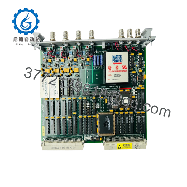
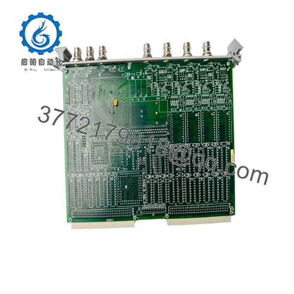
The GE VMIC VMIVME-3120 is a precision 6U VMEbus analog input board engineered for specialized, high-speed data acquisition loops where signal integrity is paramount. Featuring four fully differential channels backed by high-performance instrumentation amplifiers, the VMIVME-3120 excel at catching small-signal voltage fluctuations in environments plagued by high common-mode noise. This module is widely utilized across legacy military flight simulation systems, aerospace telemetry platforms, and turbine blade vibration analysis arrays requiring tight, deterministic synchronization.
Because this hardware has long since reached End-of-Life (EOL) status, sourcing a reliable replacement is one of the highest risks facing inventory managers overseeing legacy control architectures. Opting for a certified New Surplus VMIVME-3120 instead of a used or refurbished unit eliminates the threat of calibration drift caused by thermally stressed components or leaking analog rail capacitors. Maintaining this specialized board as a physical buffer stock on-site ensures your engineering team can instantly swap hardware during an outage, bypassing severe lead-time variability and minimizing the Total Cost of Ownership (TCO).

- VMIVME-3120
- VMIVME-3120
Installation & Configuration Guide
Stage 1: Pre-Installation (Prep & Safety)
- Isolate power to the VMEbus rack assembly. Follow strict lock-out/tag-out (LOTO) field procedures.
- Put on an ESD-safe wrist strap properly grounded to an unpainted portion of the enclosure chassis to protect the board’s high-impedance input field-effect transistors (FETs).
- Document the precise baseline settings of all PCB surface components, paying close attention to address selection headers (A16 vs. A24 spaces) and gain resistor configurations.
- Align the jumper sets on your incoming New Surplus VMIVME-3120 to mirror the failed unit’s profile precisely.
Stage 2: Removal
- Unfasten the captive retention screws anchoring the upper and lower edges of the front panel.
- Carefully label and disconnect the shielded analog input cables from the front panel interfaces to prevent cross-channel wiring errors upon reassembly.
- Pivot the top and bottom ejector handles outward with even pressure to unseat the card from the backplane J1/J2 tracks.
- Slide the module smoothly out of the guide rails and package it immediately into an ESD-protective shield bag.
Stage 3: Installation (Clone & Seat)
- Inspect the backplane slot with a flashlight to verify that no connector contacts are bent, oxidized, or contaminated with dust.
- Slide the newly jumpered VMIVME-3120 board into the matching chassis guides.
- Push firmly until the ejector arms contact the outer rim of the chassis housing, then snap both levers inward simultaneously to lock the board into the backplane.
- Secure the captive screws on the front panel to ensure a reliable ground path to the rack chassis.
Stage 4: Power-On & Testing
- Re-terminate the shielded analog signal lines to their corresponding front panel input connectors.
- Clear all LOTO devices and apply operational system power to the VME chassis enclosure.
- Verify that the system boot routine completes without throwing a VME Bus Error (BERR) on the main CPU diagnostic log.
- Run an initial hardware offset calibration script through your control software to confirm that the analog-to-digital converter (ADC) registers resolve baseline voltages correctly.
Firmware/Software Versions & Upgrade Notes
The VMIVME-3120 functions as a direct, register-mapped peripheral within VME short I/O address structures. It contains no flash microcode, programmable logic array firmware, or field-upgradable software layers.
⚠️ CRITICAL INTEGRATION WARNING: Analog gain steps and channel timing parameters are hardwired to the physical configuration of the board’s onboard component layout.
If your real-time processing application expects specific operational ranges (such as a ±10 V full-scale input deflection), replacing a module that was populated with custom gain resistors with a standard factory configuration will cause immediate signal clipping or scaling errors. Always check the exact resistor pack part numbers installed on the instrumentation amplifier stage before putting a replacement unit into active rotation.
Frequently Asked Questions (FAQ)
Why select a New Surplus VMIVME-3120 over a lower-priced refurbished board?
Analog data acquisition boards are highly sensitive to thermal aging. Refurbished boards often suffer from internal component degradation—specifically, subtle variations in precision resistor networks and degradation in power filtering capacitors. This results in signal drift, increased channel-to-channel crosstalk, and calibration loss. Our New Surplus inventory delivers factory-original calibration baselines and zero component wear, providing an expected lifespan of 10 to 15 years.
Can I hot-swap this analog input module while the VME chassis is powered up?
No. The legacy VMEbus specification utilized on the VMIVME-3120 lacks the mechanical and electrical features required for live-insertion safety. Pulling or inserting this module into a powered backplane can cause major voltage transients across the ±12 V analog power rails, which can immediately destroy the onboard instrumentation amplifiers and fault out adjacent modules.
How is the channel gain managed on the VMIVME-3120?
Channel gain is managed via a combination of software register configurations and physical resistor networks located on the PCB. The onboard instrumentation amplifiers support programmable gains of 1, 2, 4, and 8, allowing the system to scale lower-level input signals up to the optimum dynamic range of the 12-bit analog-to-digital converter.
What is the advantage of the fully differential inputs on this card?
Fully differential architectures use two signal lines per input channel (positive and negative) rather than referencing a single common ground. This design allows the input stage to reject common-mode noise—such as electrical hum or electromagnetic interference from nearby motors and power cables—ensuring that only the true sensor signal is digitized by the 12-bit ADC.
Does this board require manual calibration prior to deployment?
Every New Surplus module is physically and electrically inspected within our ESD-controlled facility to guarantee out-of-the-box hardware functionality. However, because analog components are subject to minor variances across different VME chassis backplane power supplies, we highly recommend running your system’s software-driven offset and gain calibration routines immediately following installation to ensure optimal accuracy.


