
 WhatsApp: +86 16626708626
 Email:
  Phone: +86 16626708626
Description
3. Key Technical Specifications
| Parameter | Value |
|---|---|
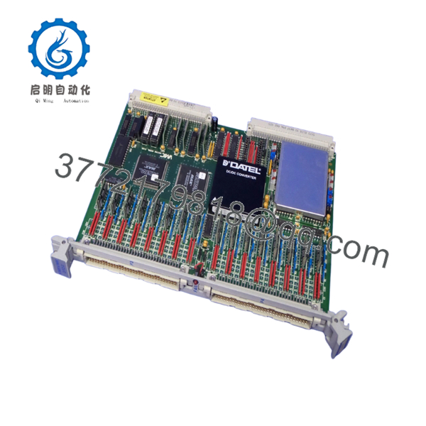
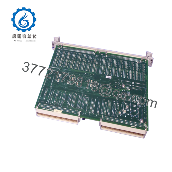
| Model Number | VMIVME 3122-010 (332-013122-010-B) |
| Manufacturer | GE Fanuc / VMIC |
| Product Type | High-Performance Analog-to-Digital Converter Board |
| Bus Interface | VMEbus |
| ADC Resolution | 16-bit |
| Input Channels | 32 Differential Analog Inputs |
| Input Connector | 96-pin Non-Latching Connector |
| Conversion Rate | Software-selectable up to 100 kHz |
| Input Ranges | 0 to +5 V, 0 to +10 V, ±2.5 V, ±5 V, ±10 V |
| Programmable Gain | x1 and x10 |
| Data Buffer | 1,024-word dual-port memory |
| Trigger Modes | Software, External, Interval Timer |
| Scan Modes | Autoscan, Single Scan, Random Access |
| Addressing | A16, A24, A32 VMEbus Address Space |
| Input Protection | Overvoltage Protected Inputs |
| Synchronization | External trigger for multi-board synchronization |
| Operating Application | Data Acquisition, Process Control, Machine Monitoring |
| Product Status | Discontinued by OEM |
The VMIVME-3122 family provides 16-bit analog acquisition with software-selectable conversion rates up to 100 kHz, programmable gain, multiple trigger modes, and support for industrial signal conditioning interfaces. The -010 variant is specifically identified as a 32-channel high-performance configuration.
4. Product Introduction
The GE VMIVME 3122-010 (332-013122-010-B) is a VMEbus-based 16-bit analog input board designed for industrial data acquisition, laboratory instrumentation, process control, and machine monitoring systems. It continuously digitizes analog signals and stores results in onboard memory, reducing host CPU overhead during high-speed acquisition tasks.
In field deployments of legacy VMIC and GE Fanuc VME systems, this module was frequently used where high channel density and deterministic sampling were required. The combination of 16-bit resolution, software-selectable conversion rates up to 100 kHz, programmable gain, and external synchronization makes it suitable for demanding measurement applications.
-

- VMIVME 3122 332-013122-010-B
- VMIVME 3122 332-013122-010-B
5. Installation & Configuration Guide
Stage 1: Pre-Installation Preparation (10 Minutes)
⚠️ Safety First
- Notify operations personnel of planned downtime.
- Verify all controlled equipment is in a safe state.
- Apply Lockout/Tagout (LOTO).
- Remove VME rack power.
- Wait at least 5 minutes for power supply discharge.
Tools Required
- ESD wrist strap
- PH1 screwdriver
- Fluke 115 multimeter
- Wire labels
- Smartphone camera
- VME rack documentation
Data Backup
- Export controller and acquisition configuration files.
- Record VME slot location.
- Document acquisition rates.
- Record scaling parameters.
- Photograph all connectors.
- Photograph jumpers and configuration settings.
Stage 2: Removing the Old Module (5 Minutes)
Steps
- Remove front-panel retaining screws.
- Label all field cables.
- Disconnect the 96-pin input connector carefully.
- Release extraction levers.
- Pull the module straight out.
⚠️ Note
Keep the original module available until commissioning is complete.
Inspection Checklist
- No bent backplane pins
- No damaged card guides
- No corrosion
- No conductive contamination
Stage 3: Installing the New Module (10 Minutes)
Steps
- Attach ESD protection before handling the board.
- Verify exact part number:
- VMIVME 3122-010
- 332-013122-010-B
- Configuration Clone (Critical)
- Replicate all jumper settings.
- Match gain configuration.
- Match addressing selections.
- Verify synchronization settings if multiple boards are installed.
- Insert module into card guides.
- Seat fully into VMEbus connector.
- Tighten front-panel hardware.
- Reconnect input cables.
Self-Checklist
- Model verified
- Jumpers matched
- Addressing verified
- Wiring secured
- Module fully seated
Stage 4: Power-On & Testing (15 Minutes)
Pre-Power Check
- Verify +5 VDC backplane supply.
- Check for shorts using a multimeter.
- Confirm cabinet grounding.
Power-On Steps
- Power up the VME rack only.
- Verify board initialization.
- Confirm VMEbus recognition.
- Verify address mapping.
- Confirm channel scan operation.
- Simulate analog input signals.
- Verify conversion accuracy.
- Confirm interrupt and synchronization functions if used.
⚠️ Troubleshooting Note
- Solid fault indication: Verify address conflicts.
- Missing channels: Check connector seating.
- Communication faults: Verify VMEbus slot configuration.
- Incorrect measurements: Verify gain and input range settings.
SOP Quality Transparency
1. Inbound Inspection & Traceability
Each VMIVME 3122-010 undergoes:
- OEM label verification
- Serial number recording
- Anti-counterfeit inspection
- Visual inspection for:
- Corrosion
- Rework marks
- Connector damage
- PCB discoloration
- Documentation audit when available
2. Live Functional Testing
Testing is performed using a genuine VMEbus test rack.
Procedures include:
- Power-on verification
- LED status verification
- VMEbus communication validation
- Analog signal simulation
- Gain switching verification
- Buffer memory verification
- External trigger verification
- Continuous operation exceeding 24 hours with thermal monitoring
An official test report can be provided upon request.
3. Electrical Parameter Testing
- 500 V Megger insulation resistance test (>10 MΩ)
- Ground continuity verification
- Backplane current measurement
- Input channel validation
4. Firmware & Configuration Verification
- Hardware revision documented
- Jumper settings recorded
- Configuration photographs archived
- Functional configuration retained for traceability
5. Final QC & Packaging
- QC inspector sign-off
- Anti-static ESD bag
- Bubble-wrap protection
- Heavy-duty export carton
- QC Passed label with inspection date
Test photos and operational videos are available upon request.
Technical Pitfall & Survival Guide
❗ Firmware Revision Mismatch
I’ve seen a replacement board pass every bench test but fail during startup because the application software expected a different hardware revision.
The resulting communication alarms consumed an entire maintenance shift.
Avoidance:
- Record board revision before removal.
- Verify compatibility with existing drivers.
- Request revision verification before shipment.
❗ DIP Switch / Jumper Misconfiguration
This remains one of the most common causes of startup failures.
Take a picture before you pull it. I can’t stress this enough.
Avoidance:
- Photograph every jumper block.
- Record gain settings.
- Record address settings.
- Verify synchronization jumpers.
❗ Terminal Block / Wiring Incompatibility
The 332-013122 variants may use different connector configurations compared to other VMIVME revisions.
I’ve seen technicians assume connector compatibility based on appearance alone.
Avoidance:
- Verify connector part numbers.
- Compare wiring diagrams.
- Check shield grounding arrangements.
❗ Power Draw Specifications
VME racks often operate near their design limits.
Adding or replacing boards without checking power budgets can cause intermittent resets that are difficult to diagnose.
Avoidance:
- Calculate total rack load.
- Maintain a minimum 20% power margin.
- Verify cooling airflow.
❗ Electrostatic Discharge (ESD)
I once watched a technician remove a VME board during a winter outage without grounding himself.
The board appeared fine but failed intermittently after startup.
Avoidance:
- Wear a grounded wrist strap.
- Use ESD-safe work surfaces.
- Store modules in anti-static packaging.
Keep these checks in mind and you’ll save yourself 90% of typical rework time.
6. Frequently Asked Questions (FAQ)
Q1. Can I hot-swap the VMIVME 3122-010?
No.
The VMIVME 3122 family was designed for conventional VMEbus environments. Removing the board under power can damage the backplane or create system-wide communication faults.
Q2. Is the 332-013122-010-B version different from the 332-013122-000 version?
Yes.
The suffix identifies a specific hardware configuration. The -010 variant is documented as a 32-channel high-performance differential input version, while other variants may have different channel counts, connectors, or filter options. Always match the complete part number.
Q3. Is this model obsolete?
Yes.
The VMIVME 3122 product family belongs to the legacy VMIC/GE Fanuc VMEbus platform and is no longer in active OEM production. Most inventory today comes from surplus stock or tested industrial spares.
Q4. Will replacing the board erase my application logic?
No.
Application logic normally resides in the controller or host processor, not in the ADC board. However, you should document acquisition settings, gain values, and scaling parameters before removal.
Q5. What sensors are commonly connected to this module?
Typical applications include:
- Thermocouples
- RTDs (through signal conditioning)
- Strain gauges
- Pressure transmitters
- Voltage monitoring circuits
- Process instrumentation signals
The board was specifically designed to interface with VMIC signal conditioning hardware.
Q6. Why is this module still purchased today?
Many power generation, aerospace test, military, transportation, and industrial facilities continue operating VMEbus systems.
Replacing a failed board is often substantially less expensive than redesigning an entire control platform.
Q7. What condition is typically available?
Most available inventory falls into one of these categories:
- New Original (New Surplus)
- Factory-Sealed Surplus
- Refurbished (Tested)
- Removed Working Spare


