
 WhatsApp: +86 16626708626
 Email:
  Phone: +86 16626708626
Description
Key Technical Specifications
| Parameter | Specification Value |
| Output Channels | 4 independent analog outputs |
| DAC Resolution | 12-Bit binary |
| Form Factor | 6U Single-Slot VMEbus |
| Settling Time | Less than 10 µs to ±0.01% of full-scale step changes |
| Output Voltage Ranges | ±10 V, ±5 V, 0 to 10 V, 0 to 5 V (software/jumper selectable) |
| Output Current Drive | ±5 mA minimum per channel |
| Monotonicity | Guaranteed monotonic over the entire operating temperature range |
| Addressing Mode | A16 or A24 short I/O space memory mapping |
| Power Requirements | +5 VDC (approx. 2.0 A), +12 VDC (approx. 0.2 A), -12 VDC (approx. 0.2 A) |
| Front Panel Interface | Shielded multi-pin or twinax connectors (variant specific) |
Product Introduction & Supply Chain Strategy
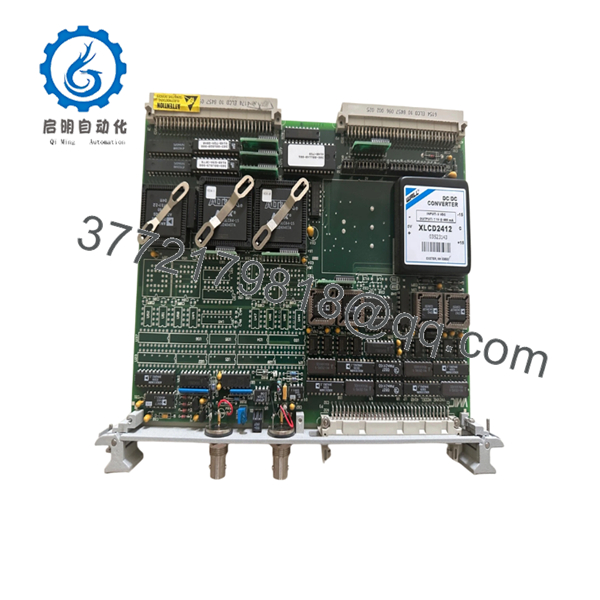
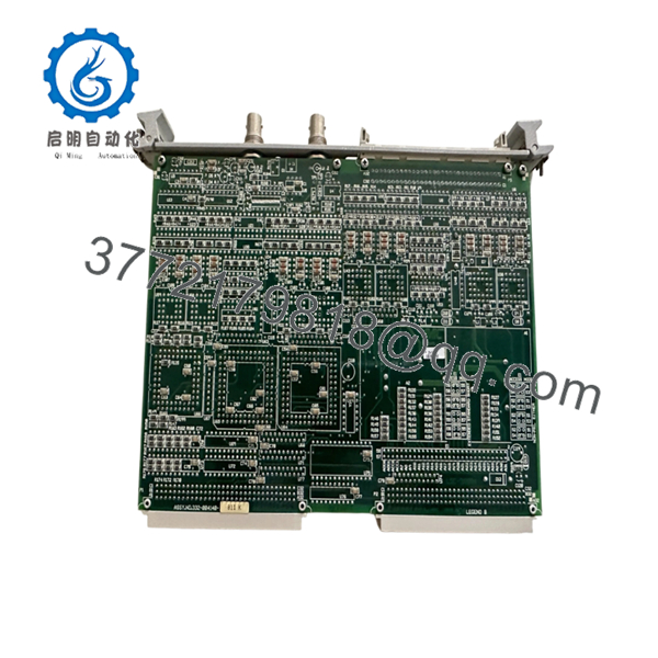
The GE VMIC VMIVME-4140-011 is a commercial-grade, high-performance 6U VMEbus analog output module featuring four independent 12-bit digital-to-analog converter (DAC) channels. Designed specifically for deterministic command loops, this card provides the precise voltage references required to modulate throttle controls, servo amplifiers, variable speed drives, and precision instrumentation inputs. Its high-speed settling circuits ensure immediate, lag-free execution of software commands dispatched by the master processing node in real-time environments like turbine monitoring and flight simulation.
Because this hardware has reached full End-of-Life (EOL) status and is no longer supported by the OEM, it poses a significant maintenance bottleneck for facility infrastructure. Acquiring a verified New Surplus VMIVME-4140-011 module acts as a critical hedge against catastrophic plant downtime. Refurbished output boards frequently suffer from DAC drift or minor component degradation that compromises calibration accuracy and risks sending erratic signals to connected field assets. Securing an unissued, original surplus board for your on-site buffer stock minimizes Total Cost of Ownership (TCO) and insulates your system from the unpredictability of second-hand hardware failures.

- VMIVME-4140-011
- VMIVME-4140-011
Installation & Configuration Guide
Stage 1: Pre-Installation (Prep & Safety)
- Completely power down the VMEbus chassis and secure the circuit breakers using standard lock-out/tag-out (LOTO) protocols.
- Put on an ESD-safe wrist strap securely grounded to an unpainted, metallic surface on the enclosure framework.
- Review and map all physical configuration jumpers on the failed module, verifying base register addressing parameters and output range settings (e.g., ±10 V vs. 0 to 10 V).
- Configure the jumper arrays on the incoming New Surplus VMIVME-4140-011 to mirror the existing board configuration exactly.
Stage 2: Removal
- Unfasten the captive upper and lower front-panel retention screws.
- Disconnect and label all analog output cable connections from the front panel interface to ensure correct field channel mapping upon reassembly.
- Pivot the top and bottom ejector wings outward with balanced force to disengage the module from the J1/J2 backplane slots.
- Smoothly pull the board straight along the card guide tracks and place it immediately inside a static-shielding bag.
Stage 3: Installation (Clone & Seat)
- Inspect the backplane slot pins with a flashlight to ensure they are clean, free of dust, and undamaged.
- Slide the newly jumpered VMIVME-4140-011 board into the designated chassis slot guides.
- Push firmly until the ejector levers contact the chassis frame, then pivot both levers inward simultaneously to seat the module’s connectors securely into the backplane.
- Tighten the captive screws on the front panel to establish structural grounding.
Stage 4: Power-On & Testing
- Re-terminate the analog output signal cables to their respective front panel interfaces.
- Clear all LOTO devices and apply system power to the VMEbus rack assembly.
- Monitor the initialization diagnostic logs to ensure the host CPU detects the new module’s address space without triggering a VME Bus Error (BERR).
- Execute your system’s diagnostic software routine to command a midpoint voltage output (e.g., 0.00 V on a ±10 V scale) and verify the output at the field terminal blocks using a calibrated digital multimeter.
Firmware/Software Versions & Upgrade Notes
The VMIVME-4140-011 acts as a register-mapped peripheral within the VME short I/O address allocations (A16/A24 spaces). The module functions completely at the hardware layer and contains no field-flashable operating system firmware, microcode, or programmable logic array software.
⚠️ CRITICAL INTEGRATION WARNING: The “-011” suffix designates a specific factory build profile that determines the baseline output voltage limits and default startup states (typically forcing the outputs to a safe 0.00 V state upon initial power-on).
If you replace this board with a different VMIVME-4140 variant suffix, the startup output profile may default to open-circuit or full-scale states. This can cause downstream actuator jumps or emergency trip conditions before the host application software takes active control of the bus. Always verify that your software application’s driver handles initial register zeroing to match the specific characteristics of the -011 hardware profile.
Frequently Asked Questions (FAQ)
What practical benefit does buying a New Surplus VMIVME-4140-011 offer over a cheaper refurbished unit?
Analog output modules are highly sensitive to component aging. Refurbished boards often contain operational amplifiers and DAC chips that have experienced years of thermal stress, which can lead to drift, output calibration errors, and reduced noise rejection. Our New Surplus hardware delivers original factory-grade performance and pristine electrical properties, providing an expected service life of 10 to 15 years without unexpected signal degradation.
Can this analog output board be hot-swapped while the VME rack is live?
No. Standard VMEbus specifications do not support live insertion or removal of modules. Pulling or inserting the VMIVME-4140-011 while backplane power is active can cause severe transient voltage spikes across the data lines and power rails. This risks permanently damaging the onboard digital-to-analog converters and interrupting the operation of adjacent boards in the rack.
What happens to the analog outputs if the VMEbus master processor freezes?
The module retains its last commanded digital value in its onboard register latches. If the host CPU hangs or stops scanning the bus, the VMIVME-4140-011 will continue to output the last valid voltage level until the chassis power is cycled or a system reset signal is pulled low across the VME backplane lines.
How is the hardware calibrated for optimum voltage accuracy?
The module features precision multi-turn trim potentiometers located directly on the circuit board surface for offset and gain calibration across individual channels. While our New Surplus boards retain their original factory baselines, we recommend performing a routine loop verification using your system’s software-driven calibration commands after installation to account for the unique power rail tolerances of your specific VME chassis.
What kind of testing does this module undergo before shipment?
Every New Surplus module is thoroughly inspected within our ESD-safe facility. We verify perfect mechanical alignment of the backplane connectors, confirm that the trace surfaces and components are free of oxidation or age-related wear, and ensure that the onboard jumper sets match the original factory configuration standards prior to secure packaging.


