
 WhatsApp: +86 16626708626
 Email:
  Phone: +86 16626708626
Description
Key Technical Specifications
- Form Factor: VME 6U single slot PCB
- Function: Optical extender for VMEbus or related signals
- Interface: Fiber optic transmit and receive channels
- Fiber Type: Multimode fiber (typical for series)
- Data Transfers: Supports extension of digital or bus signals over fiber
- Addressing/Configuration: DIP switches or onboard settings for mode
- Built-in Features: Signal regeneration and isolation via optics
- I/O Interface: Front panel fiber connectors
- Operating Temperature: 0°C to 60°C (standard for VMIVME series)
- Power Requirements: Draws from VMEbus backplane (+5V typical)
- Connectors: Fiber optic ST or similar front panel ports

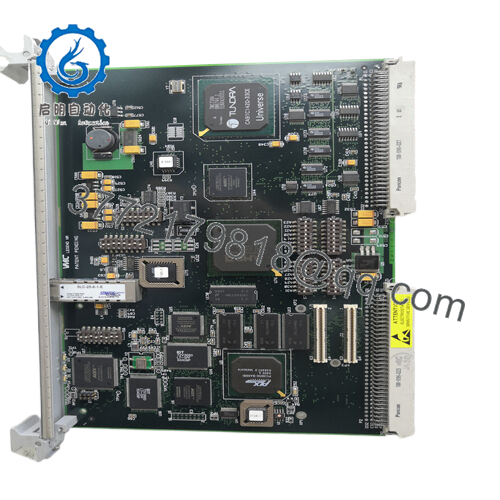
- VMIVME-5530M (332-000131-B)
Product Introduction
The GE VMIVME-5530M with assembly number 332-000131-B is a VMEbus optical extender board designed to transmit signals over fiber optic cable. It extends VME or related digital signals beyond standard backplane distances while providing electrical isolation.
In VME systems I have commissioned, this board solves distance and noise problems in large or distributed racks. Engineers choose it for the optical isolation that protects against ground loops and EMI, along with reliable signal regeneration. It serves as a direct replacement in legacy VMIC/GE VME installations that require fiber extension for bus signals or I/O.
Installation & Configuration Guide
Stage 1: Pre-Installation Preparation (10-15 minutes) ⚠️ Safety First: Notify operations of scheduled downtime. Verify the system is in a safe state, perform lock out/tag out on power supplies, and wait 5 minutes for capacitor discharge. Tools Required: Grounded ESD wrist strap, PH1 or PH2 screwdriver, digital multimeter, fiber cleaning kit, wire/fiber labels, smartphone for photos. Data Backup: Photograph front panel fiber connections, record any DIP switch or jumper settings, and note current configuration in your VME controller software.
Stage 2: Removing the Old Module
- Remove the front bezel or cover if present.
- Label the transmit (TX) and receive (RX) fiber cables before disconnection. Disconnect fiber cables carefully and cap ends to prevent contamination.
- Release the VME locking tabs or ejector handles and pull the board straight out to protect backplane pins.
- Inspect the backplane connectors for bent pins or dust.
⚠️ Keep the old module for reference until the new one runs without issues.
Stage 3: Installing the New Module (10 minutes)
- Wear your ESD strap and work on an ESD-safe surface. Confirm the replacement matches VMIVME-5530M (332-000131-B) exactly.
- Configuration Clone (Crucial): Set DIP switches or jumpers on the new board to match the photographed settings from the old unit.
- Align the board with the slot guides and insert it firmly into the VME rack until fully seated. Secure the front panel screws or tabs.
- Clean fiber ends and reconnect TX and RX cables in the exact original order.
Self-Checklist: [ ] Configuration settings match, [ ] Board fully seated and locked, [ ] Fiber cables reconnected and cleaned.
Stage 4: Power-On & Testing (15-20 minutes) Pre-Power Check: Use a multimeter to verify no shorts on the VME power rails. Power-On Steps:
- Apply power to the VME rack only.
- Observe board operation through host diagnostics.
- Verify fiber link status and signal integrity across the extended path.
- Run system-level tests to confirm extended signals propagate correctly.
- Monitor for errors in data or timing on the extended segment.
⚠️ Troubleshooting Note: If the link fails, check fiber polarity, cable continuity, cleanliness, and attenuation. Dirty or bent fiber ends cause most issues. Reconfirm configuration settings if signals do not extend properly.
Frequently Asked Questions (FAQ)
Can this module be hot-swapped under power? No. The VMIVME-5530M does not support hot-swap. Removing or inserting the board with power applied risks damage to the VME backplane or the module. Always remove rack power first.
Is the VMIVME-5530M obsolete, and is the stock genuinely new? Yes, this is a legacy VMIC/GE design now under Abaco Systems. Units offered as New Original or New Surplus come from verified excess or sealed inventory. Each board undergoes inbound inspection, functional testing on a VME rack with fiber simulation, and documentation of results. Confirm exact revision compatibility with your fiber plant and system.
What serves as a direct replacement if this board is out of stock? Abaco Systems may list updated optical extender equivalents. Verify fiber type, distance rating, and signal compatibility. Many legacy VME racks continue to use the VMIVME-5530M (332-000131-B) for exact form, fit, and optical performance.
Will I lose my programming or configuration when I replace the extender board? No. The VMIVME-5530M is a signal extender. Your application logic and VME configuration reside in the processor or controller. After physical swap and fiber reconnection, the existing setup should continue to operate.
Why is the price lower than current OEM list pricing? These units come from factory-sealed surplus or authorized excess stock channels. We do not apply full current-production pricing to legacy optical extender parts. All boards receive the same rigorous inbound verification, live functional testing with fiber link checks, and electrical parameter verification.
Does the board support multimode fiber only? Yes, the standard configuration uses multimode fiber. Confirm your cable plant matches the supported distance and wavelength before installation.
How long is the warranty on this module? We provide a 1-year warranty from shipment date on tested New Surplus or New Original units. This covers functional failures under normal operating conditions. Test videos and photos are available upon request before shipment.


