
 WhatsApp: +86 16626708626
 Email:
  Phone: +86 16626708626
Description
Key Technical Specifications
| Parameter | Specification |
| Model Code | GHOPC-410 B |
| Manufacturer Part Number | AAV66870 |
| Conventional Thermal Current (I_{th}) | 410 A |
| Rated Insulation Voltage (U_i) | 690 V |
| Rated Impulse Withstand Voltage (U_{imp}) | 6 kV |
| Coil Voltage (DC) | 196 VDC |
| Coil Voltage (AC Equivalent) | 230 VAC (using integrated/external bridge rectifier) |
| Number of Main Poles | 1 Pole (Single Busbar Connection) |
| Standards Compliance | IEC/EN 60947-4-1, CE Certified |
| Origin | Made in Italy |
Product Introduction & Supply Chain Strategy
The Ghisalba GHOPC-410 B (AAV66870) is a high-performance, compact single-pole power contactor designed for demanding switching applications where high continuous current carrying capacity and thermal resilience are paramount. Engineered and manufactured in Italy, this contactor is widely deployed in high-power DC busbars, solar/wind inverter systems, industrial battery energy storage systems (BESS), and heavy DC motor control arrays.
In high-power industrial environments, contactor degradation—such as contact pitting, high contact resistance, or coil insulation burnout—can lead to severe thermal events, system trips, or unplanned facility shutdown. Sourcing genuine, verified Ghisalba GHOPC-410 B replacement units ensures optimal contact pressure, low electrical resistance, and exact mechanical drop-in capability. Maintaining site buffer stock prevents long production lead times and protects high-value industrial power infrastructure against extended downtime.
Installation & Configuration Guide
1.Pre-Installation & Electrical Safety:Perform Lock-Out/Tag-Out and verify zero energy state.
Disconnect and isolate all primary high-voltage busbars and auxiliary coil control power. Verify zero voltage on main power terminals using a calibrated multimeter before touching busbar connections.
2.Removal of Legacy Unit:Disconnect coil leads and unbolt main busbar terminals.
Unplug or unscrew the auxiliary coil wiring. Carefully unbolt the heavy copper busbar conductors from the contactor’s main terminals, ensuring surrounding insulation and structural mountings are protected from stress.
3.Physical Installation & Wiring:Mount new contactor and torque main power terminals.
Secure the GHOPC-410 B firmly to the mounting base. Bolt the main power busbars to the contactor terminals using correct torque settings to minimize electrical contact resistance. Reconnect the 196 VDC / 230 VAC coil leads.
4.Testing & Commissioning:Check coil resistance and execute initial switching test.
Verify coil winding resistance using a DMM to ensure continuity. Apply control voltage to verify clean, rapid contact closure without chatter. Reapply main power and monitor thermal performance under load.
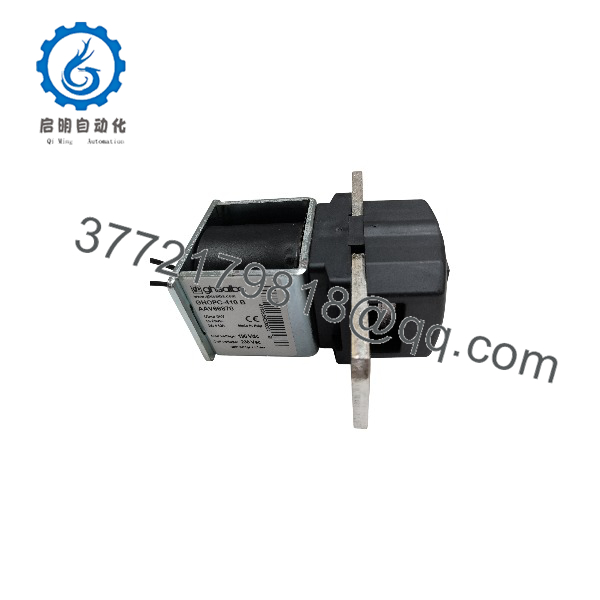
GHOPC-410 B AAV66870
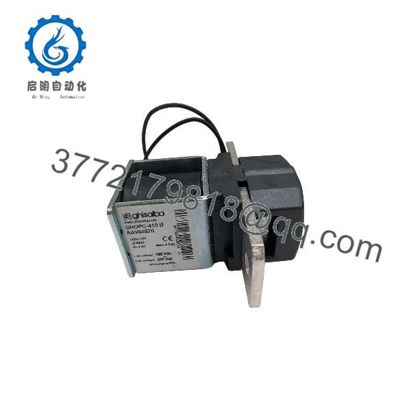
GHOPC-410 B AAV66870
Coil Circuit & Drive Notes
- Coil Operating Parameters: The solenoid coil operates natively at 196 VDC. When controlled via standard AC supply lines, it requires a 230 VAC source connected through an appropriate bridge rectifier circuit.
- Surge Suppression: Ensure adequate RC networks or flyback diodes are integrated across the coil control circuit to suppress inductive voltage spikes during contact opening.
- Thermal Consideration: Maintain adequate clearance around the terminal busbars to ensure natural convection cooling under high continuous currents up to 410A.
Frequently Asked Questions (FAQ)
Q: Can the GHOPC-410 B be used on standard 230 VAC control circuits?
A: Yes. The contactor coil operates on 196 VDC natively, which corresponds directly to a rectified 230 VAC input when connected via a full-wave bridge rectifier.
Q: What is the continuous current rating of the Ghisalba GHOPC-410 B?
A: It features a conventional free-air thermal current (I_{th}) rating of 410 Amperes.
Q: Where is this model typically used in industrial automation?
A: It is commonly installed in high-power DC drives, industrial UPS systems, solar central inverters, railway/traction power panels, and battery management systems (BMS).
Q: Why is it important to replace a worn power contactor immediately?
A: Worn contact surfaces increase contact resistance, generating extreme local heat under high current load (410A). This can cause contact welding, terminal damage, or fire hazards within power cabinets.



