
 WhatsApp: +86 16626708626
 Email:
  Phone: +86 16626708626
Description
Key Technical Specifications
| Parameter | Value |
| Supply Voltage | 24 VDC nominal (20 to 30 VDC), reverse polarity protected |
| Current Consumption | 80 mA typical with four 350 \Omega load cells connected |
| Hazardous Area Input | Zone 0 (Zone 20), Division 1 from strain gauge signals |
| Load Cell Support | Up to 4 \times 350 \Omega (or 6 \times 450 \Omega, or 12 \times 1000 \Omega) in parallel |
| Bridge Supply Voltage | 4.5 V nominal with remote sensing capability |
| Input/Output Range | \pm 18 mV nominal span (\pm 22 mV overrange) |
| Calibration Accuracy | \le \pm 0.003% of full scale |
| Linearity Accuracy | \le \pm 0.002% of full scale |
| Galvanic Isolation | 1.5 kV (I.S. In/Out, I.S. In/Supply), 500 V (Out/Supply) |
| Fault Detection | Front panel red LED indication for broken field wiring |
| Mounting / Dimensions | Standard EN/IEC60715 TH 35 DIN Rail |
Product Introduction & Supply Chain Strategy
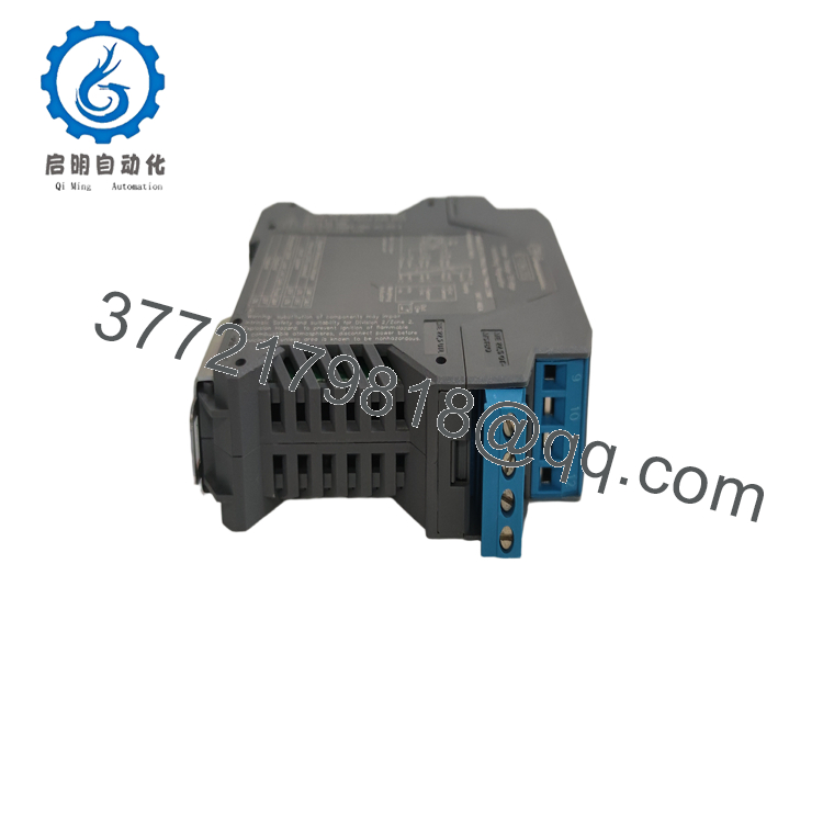
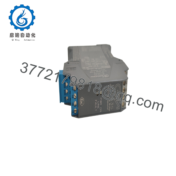
The GM International D1063S is a high-precision, single-channel intrinsically safe galvanic isolator designed to interface between weighing indicators located in the Safe Area and strain gauge load cells positioned in Hazardous Locations (Zone 0/20, Class I, Division 1). Functioning as a “transparent” repeater, the module provides a fully floating excitation voltage with remote sensing to the field assets, while cleanly feeding the millivolt (mV) weight signals back to the control system. This ensures that the safe-area weighing controller interacts with the barrier exactly as it would with a single, directly wired load cell without sacrificing telemetry fidelity.
Maintaining this module as New Surplus is a necessary practice to manage your facility’s Total Cost of Ownership (TCO). Because the D1000 series is in an active product phase-out lifecycle status, direct factory supply channels are becoming restricted, driving up lead time variability. Utilizing second-hand or refurbished safety barriers introduces unmitigated secondary costs; invisible microscale degradation of galvanic insulation barriers compromises intrinsic safety parameters (U_o, I_o, P_o), exposing hazardous gas or dust zones to spark-level energy faults. Keeping 1–2 factory-sealed surplus repeaters as buffer stock ensures instant compliance maintenance during system hardware faults, avoiding forced engineering migrations to newer platforms.

- D1063S
- D1063S
Installation & Configuration Guide
Stage 1: Pre-Installation (Prep & Safety)
- De-energize the 24 VDC power bus or individual rack terminals feeding the isolator slot. Ensure the primary weighing indicator equipment is completely powered down.
- Ensure your ESD wrist strap is grounded to the metal control panel rail before removing the unit from its packaging to protect the internal surface-mount components.
- Review the side-mounted DIP switch matrix on the new module. Configure the switches to match your system’s excitation requirements (selecting either the internal 10 V reference or external host system supply).
- Review the field parameters to verify that the collective capacitance (C_i) and inductance (L_i) of the attached load cell group do not exceed the certified entity boundaries (U_o = 17.3 V, I_o = 199.6 mA).
Stage 2: Removal
- Unplug the polarized, plug-in screw terminal blocks from the top and bottom of the housing card. Do not pull directly on the terminal wires.
- Insert a flathead screwdriver into the bottom DIN rail release clip slot.
- Lever the release clip downward slightly to unlock the housing base from the TH 35 DIN rail.
- Tilt the module upward and remove it completely from the mounting panel slot.
Stage 3: Installation (Clone & Seat)
- Hook the upper rear retaining tab of the new surplus D1063S onto the top edge of the DIN rail.
- Push down and snap the lower portion of the housing forward until the spring-loaded rail clip locks firmly over the bottom lip of the rail track.
- Insert the original polarized terminal plugs into their corresponding sockets (Hazardous Area terminals 9–16 at one end, Safe Area/Supply terminals 1–8 at the other).
- Tighten the terminal block screws to a maximum torque of 0.5 N·m (4.4 lb·in) to secure the lines against ongoing plant vibrations.
Stage 4: Power-On & Testing
- Apply 24 VDC control power to the supply lines. Verify that the front panel green “PWR ON” LED lights up steadily.
- Check the front red “FAULT” LED. If it illuminates, check for an open-circuit or broken sense/excitation wire in the hazardous field circuit.
- Apply a known test weight configuration to the active scale platform.
- Check the safe area weighing terminal interface to ensure the repeated mV bridge signal mirrors the applied mass linearly, matching the module’s high-precision 0.003% calibration specification.
Firmware/Software Versions & Upgrade Notes
The D1063S operates as an analog-transparent hardware device rather than an executable software processor platform. It does not carry flashable microcode or microprocessor firmware versions.
However, because it is in a manufacturer phase-out cycle, GM International recommends the D5263S as its future direct functional alternative. When managing replacement stocks, remember that while the core functional metrics match, the D5263S utilizes a different chassis footprint and terminal connection array. Swapping modules requires careful checking of terminal cross-references to ensure you do not map input wiring lines to the wrong pins during field retrofits.
Frequently Asked Questions (FAQ)
Q: What makes this module “transparent” to our existing safe-area weighing indicator?
A: The D1063S copies the excitation reference voltage supplied by the safe-area host indicator, isolates it, and projects it out to the hazardous-area load cells. It then reads the returning millivolt output from the scale and mirrors that exact signal back to the indicator’s input terminals. To the weighing controller, the barrier is electrically invisible, functioning exactly like a direct cable link.
Q: Can I replace an active D1063S with a standard, non-isolated signal amplifier?
A: Absolutely not. The D1063S is a safety-certified, intrinsically safe associated apparatus. It acts as an energy-limiting barrier that prevents high voltage or fault currents from entering explosive atmospheres (Zone 0/20). Replacing it with a non-certified device removes your explosion protection and breaks local facility safety compliance laws.
Q: Why should our plant purchase New Surplus GMI barriers instead of standard refurbished ones?
A: Intrinsic safety equipment requires absolute electrical component integrity. Refurbished or used components can have internal trace tracking wear, compromised galvanic isolation barriers, or stressed internal zener diodes from previous power surges. A refurbished failure could allow unsafe energy levels into an explosive hazard zone, risking catastrophic accidents. Buying New Surplus ensures factory-level isolation protection at a lower cost than current OEM lines.
Q: How many load cells can I wire in parallel to a single D1063S module?
A: The module’s internal power delivery system can drive up to four 350 \Omega load cells, six 450 \Omega load cells, or up to twelve 1000 Ω load cells connected in parallel. Ensure the combined draw does not exceed the unit’s maximum current output configuration.
Q: What type of logistical coverage applies to this surplus barrier component?
A: We provide a comprehensive 12-month operational replacement warranty starting from your logistics delivery date. This ensures your surplus unit will operate identically to factory-new performance criteria, giving your procurement and engineering teams total peace of mind.



