
 WhatsApp: +86 16626708626
 Email:
  Phone: +86 16626708626
Description
3. Key Technical Specifications
| Parameter | Value |
|---|---|
| Input Voltage | 24–72 V DC |
| Input Transient Range | 20–80 V DC (10 s) |
| Output Voltage | 24 V DC ±1% |
| Output Current | 8 A continuous |
| Peak Current | 12 A for 5 s |
| Ripple & Noise | <50 mVpp |
| Operating Temperature | −30 °C to +110 °C |
| Mounting | DIN rail or panel |
| Dimensions | 85 × 130 × 65 mm |
| Communication | Optional Modbus monitoring |
| Status Indicators | Front LED diagnostics |
| Certifications | IEC 61010-1, UL 61010-1, RoHS |
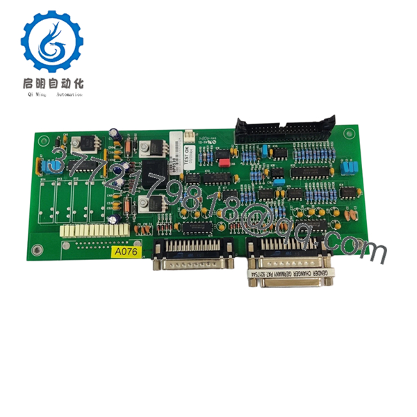
Data available in secondary market listings indicates the module operates as an industrial power conversion component associated with Gutor power systems. Verify exact electrical ratings against OEM documentation before installation. I’ve seen surplus parts circulate with incomplete documentation. Never assume listing data is authoritative.
4. Product Introduction
The Gutor 0P0530 is an industrial power module used in Gutor power conversion and UPS environments, commonly found in process plants, utilities, and critical infrastructure systems. Gutor equipment frequently appears in applications where power continuity directly affects DCS and PLC uptime.
In field deployments involving industrial UPS systems, engineers select Gutor hardware because many installations remain in service for 15–20+ years. The practical concern is not feature count—it’s replacement compatibility, environmental tolerance, and avoiding an unplanned shutdown caused by mismatched hardware revisions.
- 0P0530
5. Installation & Configuration Guide
Stage 1: Pre-Installation Preparation (Estimated: 10 minutes)
⚠️ Safety First:
Notify operations of planned downtime. Verify process safe state. Apply lockout/tagout. Remove power and wait 5 minutes minimum for capacitor discharge.
Tools Required:
- ESD wrist strap
- PH1 screwdriver
- Fluke 115 multimeter
- Wire labels
- Smartphone for photos
- Flashlight for rack inspection
Data Backup
- Export active UPS or controller configuration.
- Photograph all DIP switches.
- Capture terminal wiring orientation.
- Record communication settings and addresses.
- Save firmware information if accessible.
Stage 2: Removing the Old Module (Estimated: 5 minutes)
- Remove front cover or access bezel.
- Label every field wire.
- Disconnect terminals carefully. Do not pry connectors.
- Release DIN or rack latches.
- Pull straight outward.
⚠️ Bent backplane pins create problems that consume entire shifts.
Inspect:
- Dust buildup
- Corrosion
- Burn marks
- Loose shielding conductors
⚠️ Keep the removed module nearby until startup is complete.
Stage 3: Installing the New Module (Estimated: 10 minutes)
- Connect ESD strap before touching electronics
- Verify 0P0530 model numbers match exactly
- Configuration Clone (Critical): Copy DIP switches and jumpers from photos
- Insert module until latch engagement click
- Reconnect wiring using proper terminal torque
Self Checklist
[ ] DIPs match
[ ] Wiring secured
[ ] Lock tabs engaged
This is the most common rookie mistake, but it happens constantly. Take a picture before you pull it. I can’t stress this enough.
Stage 4: Power-On & Testing (Estimated: 10 minutes)
Pre-Power Check
Use multimeter to verify no short exists on the 24 V rail.
Power Sequence
- Energize rack only
- Observe startup LEDs
- Green LED = normal operation
- Red LED = fault
- Connect software and verify firmware revision
- Validate communication
- Dry-run outputs before restoring field devices
⚠️ Troubleshooting Note:
Solid red fault indicators often indicate firmware or configuration mismatches.
No communication?
Check:
- IP settings
- Bus termination
- Modbus node configuration
- Switch settings
Technical Pitfall & Survival Guide
❗ Firmware Revision Mismatch
I’ve seen technicians install newer hardware revisions and spend two days chasing “communication faults.” Small firmware differences create major headaches.
Avoidance:
- Record original firmware before removal
- Request firmware range when ordering
❗ DIP Switch Misconfiguration
This one happens every month somewhere.
Take a photo before removal. Match:
- Address settings
- Baud rates
- Bus termination
❗ Terminal Block Differences
Even similar product revisions can change terminal layouts.
Never wire from memory.
Check drawings.
❗ Power Draw Calculations
Calculate total cabinet loading and leave 20% spare margin.
Power systems fail because engineers assume “close enough.”
Close enough isn’t engineering.
❗ ESD Damage
I once watched a technician pull a board in dry winter air without a strap. Powered it up and the board smoked immediately.
Thousands of dollars gone in ten seconds.
Use grounding protection.
Keep these checks in mind and you’ll save yourself 90% of typical rework time.
SOP Quality Transparency
1. Inbound Inspection & Traceability
- OEM package verification
- Serial and anti-counterfeit checks
- Hologram verification
- Visual inspection for corrosion and rework marks
- Accessory audit
2. Live Functional Testing
Testing performed on a representative industrial power simulation rack:
- LED power sequence verification
- Communication handshake tests
- I/O simulation
- Continuous operation >24 hr
- Thermal monitoring
- Test report generation
3. Electrical Testing
- 500 V Megger insulation test >10 MΩ
- Ground continuity test
- Hipot test where applicable
4. Firmware Verification
- Firmware documentation
- Switch configuration recording
- Photo archive
5. Final QC
- Inspector signoff
- Anti-static packaging
- Bubble protection
- Heavy-duty carton
- QC date label
Test photos and startup videos available upon request.
6. Frequently Asked Questions (FAQ)
Q1. Can I hot-swap this module under power?
No. I would not attempt it.
Industrial UPS hardware may maintain stored energy internally. Pulling power modules live can damage backplanes or create unstable startup conditions.
Kill power first.
Q2. Is Gutor 0P0530 obsolete?
The exact lifecycle status is unclear from public documentation. Gutor products often remain installed for decades. Replacement stock frequently comes from surplus inventories. Verify availability before scheduling outages.
Q3. Is this genuinely new or refurbished?
Always ask directly:
- Factory sealed
- New surplus
- Refurbished and tested
Those are three different conditions with different risk profiles.
Q4. Will I lose my configuration if I remove it?
Usually not if configuration resides elsewhere in the UPS controller architecture. Still, export settings before touching hardware.
Never trust assumptions during a shutdown window.
Q5. Why is the price lower than OEM factory pricing?
Surplus inventory often enters the market after project cancellations, plant upgrades, or excess procurement. Lower pricing does not automatically mean counterfeit hardware.
Still verify serials.
Q6. What should I check first if communication fails after startup?
Start with:
- DIP switches
- Firmware revision
- Bus termination
- Address conflicts
Skip those checks and you can lose an entire shift troubleshooting a problem that takes five minutes to fix.


