
 WhatsApp: +86 16626708626
 Email:
  Phone: +86 16626708626
Description
Key Technical Specifications
| Parameter | Value |
|---|---|
| Model Number | F3240 |
| Manufacturer | HIMA Paul Hildebrandt GmbH |
| Product Family | HIQuad F3200 series |
| Product Type | Safety-related high-voltage digital input module |
| System Compatibility | HIMA HIQuad H41q and H51q safety systems |
| Input Channels | 16 testable digital input channels |
| Nominal DC Input | 110 V DC |
| Nominal AC Input | 127 V AC, single phase |
| Common Market Description | 120 V AC/DC safety digital input module |
| Input Signal Type | Binary field signals from contacts, switches, relay outputs, and sensors |
| Switching Threshold | Approximately 45 V |
| Input Current | Less than 1 mA |
| Signal-to-Data Response | Approximately 50 ms |
| Logic Selection | Positive or negative logic, configuration dependent |
| Channel Diagnostics | Automatic operational self-test, including crosstalk and filter-capacitor checks |
| Isolation | Safe electrical separation between field inputs and system bus |
| Backplane Supply | 5 V DC, approximately 100 mA |
| System Supply | 24 V DC, approximately 120 mA |
| Safety Integrity Capability | Up to SIL 3, application dependent |
| Machinery Safety Capability | Up to Category 4 / Performance Level e, application dependent |
| Module Width | 4 SU / approximately 20.32 mm |
| Rack Installation | HIQuad rack/backplane with front cable plug |
| Enclosure Rating | IP20 when installed in a suitable control cabinet |
| Operating Temperature | −20 to +60 °C |
| Approximate Dimensions | 25 × 230 × 120 mm |
| Approximate Weight | 0.28 kg |
The HIMA F3240 is a high-voltage safety digital input module, not a 24 V DC F3221 substitute and not a safety controller. It accepts 110 V DC or 127 V AC discrete field signals. The 45 V switching threshold and approximately 50 ms response make it appropriate for higher-voltage contact circuits, but unsuitable for direct 24 V DC sensor inputs unless an approved interposing circuit is used.
Product Introduction
The HIMA F3240 is a 16-channel testable safety digital input module for HIQuad H41q and H51q safety systems. It monitors 110 V DC or 127 V AC field contacts used in emergency shutdown, burner management, turbine trip, fire-and-gas, and process interlock circuits.
This module fits legacy safety systems that use higher-voltage discrete wiring rather than standard 24 V DC I/O. Each channel provides diagnostic testing and safe isolation from the HIQuad system bus. Match the voltage class, terminal assignment, rack position, logic polarity, safety application, and approved wiring drawings before ordering a replacement.
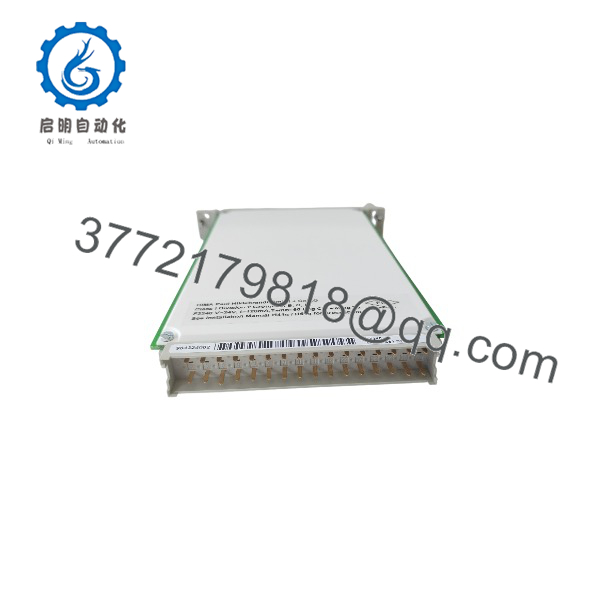
F3240
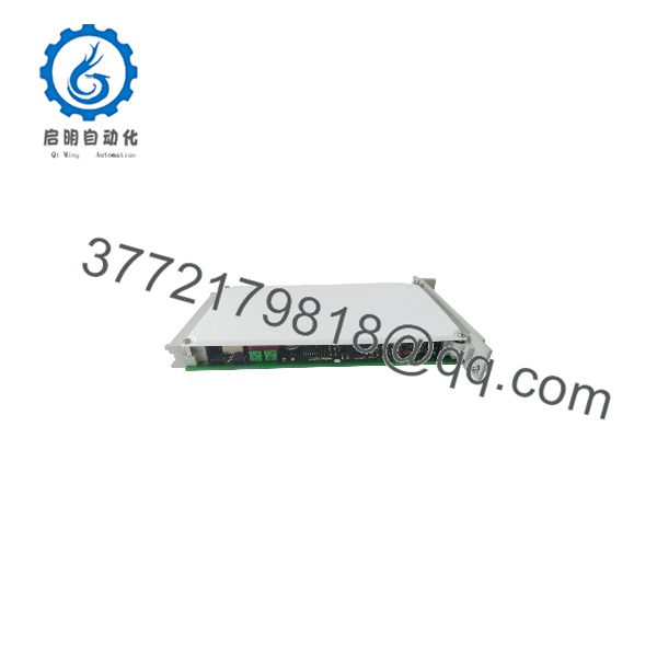
F3240
Troubleshooting Quick Reference
| Symptom | Possible Cause | Relevance to This Part | Quick Check Method | Recommendation |
|---|---|---|---|---|
| No module indication or controller reports module absent | Module not seated, bent backplane contacts, wrong rack slot, rack power fault, failed module | ✅ Medium | Isolate the rack under approved procedures; reseat the F3240, inspect backplane contacts and front connector, then read HIQuad diagnostics | Verify rack supply and mechanical seating before replacing the module |
| One input remains OFF with field contact closed | Missing 110 V DC or 127 V AC source, open field circuit, failed relay contact, loose terminal, voltage below threshold | ❌ Usually field-side | Measure the signal directly at the F3240 channel terminal using a properly rated meter; confirm it exceeds approximately 45 V and matches the approved voltage class | Repair field wiring or contact first; do not apply 24 V DC to prove a high-voltage input |
| One input remains ON with field contact open | Short to high-voltage source, welded relay contact, incorrect common wiring, cable insulation fault, failed input channel | ❌ Usually field-side | Under approved isolation procedures, remove the field conductor and observe online diagnostics; measure residual voltage at the module terminal | If the input stays ON with the field wire removed, test the channel using an approved controlled source and investigate module failure |
| Several inputs fail in one group | Lost common high-voltage supply, failed fused distribution, shared return fault, terminal plug not fully engaged | ❌ Low | Check the common 110 V DC or 127 V AC supply, group fuses, shared neutral/return, and front connector seating | Restore the shared power path before condemning the F3240 |
| Input state flickers or changes intermittently | Loose terminal, relay contact chatter, field cable vibration, moisture, induced voltage, marginal input voltage | ❌ Usually field installation | Trend channel diagnostics while measuring voltage at the terminal; inspect relay coil operation, terminal torque, junction boxes, and cable insulation | Fix the source circuit first. The approximately 50 ms response will not cure severe contact chatter or voltage loss |
| Input state is opposite of expected process condition | Positive/negative logic configured incorrectly, NO/NC contact wired incorrectly, incorrect loop drawing interpretation | ❌ Configuration or wiring | Compare the approved safety application logic with actual terminal voltage when the device is in normal and trip states | Correct the field logic or application configuration through approved change control |
| Safety trip remains active after contact is restored | Another trip remains active, reset sequence missing, discrepancy logic active, controller still sees a separate input fault | ❌ Not necessarily an fault | Use HIQuad diagnostics to find the first active trip or failed permissive; inspect all related channels | Do not replace a healthy input module to clear a valid process trip |
| Input fault begins after maintenance work | Field wires landed one terminal off, connector swapped, cable shield or neutral moved, wrong high-voltage source connected | ❌ Common installation issue | Compare wiring against pre-work photos, terminal numbers, and the approved loop drawings; check every common and fuse point | Do not wire from memory. Correct the field installation before testing the safety function |
| Replacement module is not recognized | Wrong module family, damaged backplane, incompatible slot configuration, incorrectly seated front connector | ✅ High | Compare the old and new module labels, verify model, inspect rack/backplane, and read the controller diagnostic buffer | Use an exact replacement. Do not substitute a 24 V DC input module without an approved redesign |
| Replacement module reads all channels incorrectly | Terminal block mismatch, polarity selection not restored, project configuration issue, incorrect AC/DC field-source assumptions | ✅ Medium | Photograph and compare original terminal wiring and logic settings; prove each channel with its approved field voltage | Restore original wiring and validated configuration before declaring the replacement defective |
| Module or field wiring heats abnormally | Overvoltage, damaged insulation, incorrect field supply, loose terminal generating heat, contamination | ✅ Critical | Isolate power immediately; inspect terminals, cable insulation, fuses, and input supply voltage with a properly rated instrument | Do not re-energize until the cause is corrected. Replace any heat-damaged component |
| Suspected ESD or handling damage | Module exposed during cabinet maintenance, connector pins touched, improper storage | ✅ Medium | Inspect for physical damage; test each channel in a compatible HIQuad test rack with controlled high-voltage input signals | Use ESD controls and replace only after controlled testing confirms a channel fault |
❗ Voltage-class warning: The is for 110 V DC or 127 V AC discrete signals. It has an approximately 45 V switching threshold. A standard 24 V DC input will not reliably turn it ON. Do not mix it up with the 24 V DC HIMA F3221, even though both modules provide 16 digital input channels.
❗ Meter warning: Use a meter, probes, PPE, and work method rated for the actual field voltage and installation category. A 127 V AC input circuit can remain energized through a shared neutral, failed relay, induced voltage, or incorrectly isolated source. Verify absence of voltage before moving wires.
❗ Wiring warning: Take photos of the original front connector, terminal numbers, commons, fuses, and relay-contact arrangement before removal. I have seen a technician land a shared neutral one position off after a replacement, then spend hours blaming the module because eight safety inputs appeared dead.
❗ Safety warning: The is part of a safety instrumented system. Do not bridge inputs or use temporary jumpers to suppress an ESD, burner trip, or shutdown alarm during normal production. Follow approved lockout/tagout, management-of-change, proof-test, and final-element test procedures.
If diagnostics remain unclear, contact technical support with photos of the label and connector, HIQuad rack type and slot, input circuit drawings, measured channel voltages, controller diagnostics, and the status of adjacent channels. Keep these checks in mind and you will save yourself most of the usual rework time.
Frequently Asked Questions
What is the HIMA used for?
The is a 16-channel safety digital input module for HIMA HIQuad systems. It reads higher-voltage binary field signals—110 V DC or 127 V AC—from relay contacts, switches, and protective devices, then passes those states to the HIQuad safety logic solver. Typical applications include emergency shutdown, burner management, turbine trips, fire-and-gas systems, and critical process interlocks.
Is the the same as an F3221?
No. Both are 16-channel safety digital input modules, but they work with different voltage classes. The F3221 is intended for 24 V DC signals, while the monitors 110 V DC or 127 V AC signals and has a switching threshold near 45 V. Installing the wrong module can cause every field input to read incorrectly or remain OFF.
Can I connect 24 V DC sensors directly to an ?
No. A 24 V DC signal is below the ’s approximately 45 V switching threshold, so it will not provide a valid ON state. Use the correct 24 V DC HIQuad input module or design a properly isolated interposing relay/interface circuit through an approved safety engineering change.
Do not use an improvised voltage booster or jumper arrangement. It changes the input loop’s failure behavior and can invalidate the documented safety function.
Does the accept both 110 V DC and 127 V AC?
Yes, available references identify the module for 110 V DC or 127 V AC field signals, often marketed broadly as a 120 V AC/DC testable input module. Confirm the actual field supply and approved circuit design before wiring. Do not connect a voltage outside the documented operating range based only on the “120 V” shorthand.
Can I hot-swap the ?
Do not assume it is hot-swappable. Whether it can be replaced under power depends on the installed HIQuad architecture, field wiring, cabinet design, redundancy arrangement, and written site procedure. Removing an input module can cause diagnostic faults, remove critical status feedback, initiate a trip, or reduce safety-system diagnostic coverage.
Place the process in an approved safe state, follow lockout/tagout and functional-safety maintenance procedures, document the existing configuration, replace the module, and perform required post-change proof tests.
Is the HIMA obsolete?
The is associated with legacy HIQuad safety systems, so exact replacement units are generally sourced through New Surplus, tested used, or refurbished inventory. For a critical installation, keep a verified spare, archive the HIQuad project and diagnostics, retain accurate loop drawings, and maintain a documented system-migration plan.
Before purchasing, request the actual module-label photo, confirmation of the model, condition report, test method, warranty terms, and return conditions.
What should be tested before shipping a New Surplus ?
Start with inbound inspection and traceability: verify the nameplate, serial number, front connector, backplane contacts, coding features, housing condition, and absence of corrosion, rework marks, heat discoloration, cracked components, or damaged terminals. Check supplied documentation, packaging, and accessory hardware where available.
For functional testing, install the module in a compatible HIQuad test rack with a known-good safety controller and approved test configuration. Verify module recognition and normal startup diagnostics. Apply controlled 110 V DC and, where the approved test fixture supports it, 127 V AC signals to all 16 channels. Confirm each channel changes state correctly above the switching threshold, verify OFF behavior when voltage is removed, and observe self-test diagnostics.
Run the module under power for more than 24 hours while monitoring channel stability, rack communication, temperature, and diagnostic status. Record the HIQuad rack model, input voltage, results for all 16 channels, diagnostic screenshots, test duration, and inspector sign-off. Package the unit in ESD-safe material, protect front and backplane contacts, then use heavy-duty corrugated packaging. Test photos and video should be available upon request. Available product references identify the as a 16-channel, testable HIQuad safety input module for 110 V DC or 127 V AC signals.



