
 WhatsApp: +86 16626708626
 Email:
  Phone: +86 16626708626
Description
Key Technical Specifications
| Parameter | Value |
|---|---|
| Model Number | F3331 |
| Manufacturer | HIMA Paul Hildebrandt GmbH |
| Product Family | HIQuad F3300 series |
| Product Type | Testable safety-related digital output module |
| System Application | HIMA HIQuad safety-system I/O rack |
| Digital Output Channels | 8 |
| Nominal Output Voltage | 24 V DC |
| Output Type | Safety transistor output; short-circuit protected |
| Rated Output Current | 500 mA maximum per channel |
| Rated Resistive/Inductive Load | Up to 500 mA / 12 W per channel |
| Lamp Load | Up to 4 W per channel |
| Internal Voltage Drop | 2 V maximum at 500 mA load |
| Maximum Line Resistance | 11 Ω total, outgoing plus return conductor |
| Output Leakage Current | 350 µA maximum |
| Reset-State Output Voltage | 1.5 V maximum |
| Undervoltage Shutdown | ≤16 V DC |
| Short-Circuit Detection Range | 0.75–1.5 A |
| Line-Break Detection Range | 0.5–9.5 mA |
| Minimum Load for Line-Break Monitoring | 10 mA |
| Test-Signal Duration | 200 µs maximum |
| Diagnostics | Output readback, output-stage test, cross-talk test, line monitoring |
| 5 V DC Backplane Consumption | 130 mA |
| 24 V DC Field-Supply Consumption | 180 mA, additional to connected load |
| Module Width | 4 TE |
| Safety Features | Integrated safe shutdown and safe electrical isolation |
| Maximum Modules Per I/O Rack | 10 F3331 modules at nominal load |
The F3331 is an 8-channel safety digital output module, not an analog output module and not a 24 V DC power supply. It drives final-interface loads such as interposing relays, contactors through suitable interface circuits, shutdown solenoids, annunciators, and lamp loads within its channel rating. The module automatically tests its output paths during operation and provides line monitoring where the field circuit has at least a 10 mA load.
Product Introduction
The HIMA F3331 is an eight-channel, testable 24 V DC safety digital output module for legacy HIQuad safety systems. It switches discrete loads in emergency shutdown, burner management, turbine protection, fire-and-gas, and machine safeguarding applications while monitoring output behavior for short circuits, line breaks, cross-talk, and output-stage faults.
Use the F3331 where the existing HIQuad design requires safety-rated 24 V DC output circuits with integrated safe shutdown and diagnostic feedback. Each channel supports resistive or inductive loads up to 500 mA, with a 12 W maximum load and a separate 4 W limit for lamps. Verify actual steady-state current, inrush current, field wiring, and final-element interface before replacement.
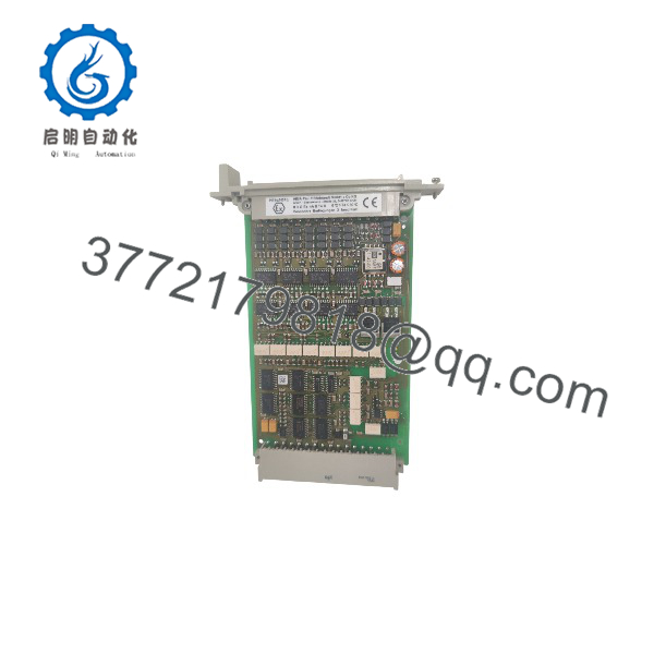
F3331
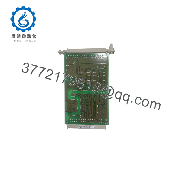
F3331
Troubleshooting Quick Reference
| Symptom | Possible Cause | Relevance to This Part | Quick Check Method | Recommendation |
|---|---|---|---|---|
| No outputs operate after module installation | Module not seated, missing 24 V DC field supply, rack backplane fault, output enable or safety logic not permissive | ❌ Low until supply and logic are checked | Measure 24 V DC at the F3331 field-supply terminals; inspect module seating and rack diagnostics; verify controller RUN state and safety permissives | Restore supply, seating, and logic conditions before replacing the module |
| One output will not energize | Safety function not permissive, external load open, blown field fuse, output wiring break, output-channel fault | ❌ Usually logic or field wiring | Review HIQuad diagnostics; measure voltage at the output terminal when commanded ON, then measure at the field load | If the module terminal switches correctly but the load does not energize, repair wiring, fuse, relay coil, or final element |
| One output remains energized after a trip command | External relay/contact welded, backfeed from another supply, wrong wiring, forced logic, failed output channel | ❌ Usually external final-element issue | Under approved lockout/tagout, verify whether voltage at the output falls to the reset-state value; isolate the external load and check for backfeed | If the module output drops but the field device remains energized, inspect the external relay, contactor, solenoid, and wiring |
| Output reports short-circuit fault | Field wire shorted to 0 V or 24 V, failed solenoid coil, damaged cable, load current exceeds channel limit | ❌ Usually field circuit | Isolate the field load and inspect cable insulation; measure coil resistance and startup current; check for a fault that exceeds the 0.75–1.5 A short-detection range | Repair the load or wiring. Do not replace the until the short is cleared |
| Output reports line break | Open field wire, disconnected load, failed relay/solenoid coil, loose terminal, load current below monitoring threshold | ❌ Usually field circuit | Check continuity through the outgoing and return conductors; measure current during commanded ON state; confirm at least 10 mA load for line-break monitoring | Repair wiring or load. Add an approved monitoring load only if the safety design permits it |
| Line-break fault appears with a low-current LED relay | Load current below 10 mA monitoring requirement | ❌ Design/application issue | Measure actual output current; compare it against the 10 mA minimum required for line-break monitoring | Use an approved interposing relay or engineered load interface. Do not bypass diagnostics casually |
| Output voltage is low under load | Excessive cable resistance, undersized wire, corroded terminal, overloaded channel, weak 24 V DC supply | ❌ Usually installation-related | Measure voltage at the output and at the load while energized; calculate total outgoing plus return resistance | Keep total line resistance at or below 11 Ω and keep the channel at or below 500 mA |
| Several outputs fail together | Lost 24 V DC field supply, common return open, terminal connector issue, shared fuse failure, overloaded supply | ❌ Low | Measure the field supply at the module and inspect shared fuses, commons, terminal blocks, and wiring | Restore the field power path before replacing the module |
| Output cycles briefly or causes a nuisance trip | Output self-test pulse interacting with sensitive load, incorrect interface relay, load inductance not suppressed, wiring noise | ✅ Medium | Review the approved output-interface design; observe with a suitable instrument; check flyback suppression at DC coils | Use a properly rated interface relay or suppression device approved for the safety circuit. Do not defeat output diagnostics |
| New shows immediate fault after swap | Wrong module type, terminal connector mismatch, damaged rack contacts, project configuration issue, field fault already present | ✅ Medium | Compare module label, rack slot, terminal wiring, and controller diagnostics; test with field loads isolated under authorized procedure | Confirm exact match and clear field faults before declaring the new unit defective |
| Cabinet fuse blows on output demand | Shorted coil, pinched cable, incorrect polarity, reverse-energy suppression failure, channel overload | ❌ Usually field-side | Disconnect loads one at a time and command outputs through the authorized test procedure; inspect coil resistance and wiring | Find and repair the external fault. Never increase fuse size beyond the approved design |
| Output reads a small residual voltage while OFF | Normal leakage current, test circuitry, meter ghost reading, external backfeed | ❌ Often normal | Measure with the specified load connected and compare to the 1.5 V reset-state maximum; verify with a low-impedance meter or test load | Do not replace the module based only on a high-impedance meter reading |
| Module is hot or repeatedly faults under demand | Aggregate load too high, multiple channels at limit, high ambient temperature, poor ventilation, aging output stage | ✅ Medium | Calculate all channel loads and rack supply burden; inspect ventilation and measure cabinet temperature | Reduce loading, correct cooling, and replace the module only if it fails under a known-good rated load |
❗ Channel-rating warning: Each output is limited to 500 mA. That includes coil inrush, not merely the relay or solenoid’s printed holding current. A valve solenoid that normally draws 350 mA but pulls 900 mA at pickup can trigger short-circuit diagnostics or damage the interface over time.
❗ Line-monitoring warning: The requires at least 10 mA load current for reliable line-break monitoring. A low-current PLC input, LED indicator, or miniature relay may energize but still trigger a line-break diagnostic. Do not “fix” this by disabling safety diagnostics without an approved engineering review.
❗ Safe-state warning: On a valid shutdown command, determine whether the output itself actually goes low before blaming the module. I have seen technicians replace a good safety output card when the real fault was a welded interposing relay feeding a shutdown solenoid from a second 24 V supply.
❗ Wiring warning: Photograph the outgoing and return terminals before removing the original module. A swapped common or a field wire landed one terminal off can make a replacement look defective immediately.
If you are stuck, send technical support photos of the label and connector, HIQuad rack slot, controller diagnostics, 24 V DC field-supply measurement, actual load current, coil resistance, and voltage measured at both the module and final element. Keep these checks in mind and you will save yourself most of the usual rework time.
Frequently Asked Questions
What is the HIMA ?
The HIMA is an eight-channel, safety-related 24 V DC digital output module for a HIQuad safety-system I/O rack. It switches field loads and continuously tests output conditions through output-signal readback, output-stage tests, cross-talk checks, and line monitoring.
What loads can the drive?
Each channel can drive a resistive or inductive load up to 500 mA, with a maximum 12 W load. Lamp loads are limited to 4 W per channel. Common applications include interposing-relay coils, small 24 V DC solenoids, annunciators, and indicator lamps, subject to the approved safety-loop design.
Before connecting a load, verify coil inrush current, holding current, inductive transient suppression, cable resistance, ambient temperature, and the final element’s safety function.
Does the provide line-break monitoring?
Yes. The module includes line monitoring, but it requires a minimum load current of 10 mA. An output circuit drawing less than that may be flagged as an open circuit even though the connected device appears to operate.
This catches technicians off guard when a legacy relay is replaced with a low-current electronic input or LED pilot light. Confirm the load-current requirement before modifying the output circuit.
Can I connect a large contactor or valve solenoid directly to the ?
Only if its complete electrical load profile stays within the 500 mA channel rating, 12 W limit, inrush capability, and approved safety design. In most critical applications, it is better to use an appropriately rated interposing relay or safety-rated final-element interface rather than drive a large coil directly from the module.
The interface must preserve the required de-energize-to-trip behavior, diagnostic coverage, suppression method, and proof-testability. Do not add a standard relay without evaluating whether it changes the safety-function calculation.
Can I hot-swap the ?
Do not assume it is hot-swappable. The controls safety-related outputs; removal can de-energize final elements, trigger an emergency shutdown, or eliminate output diagnostics. Whether live replacement is permitted depends on the exact HIQuad architecture, redundancy, site procedure, and process safe state.
Place the process in an approved safe condition, isolate power as required, record the original wiring and diagnostics, install the replacement, and carry out all required functional tests before returning the equipment to service.
Is the obsolete?
Yes, it is identified in available supplier records as discontinued and is associated with legacy HIQuad systems. Exact replacement stock is typically New Surplus, tested used, or refurbished. For an operating critical system, retain a verified spare, matching front connector, documented terminal arrangement, HIQuad project archive, and a long-term migration plan.
How should a New Surplus be tested before shipment?
Start with inbound inspection: verify the nameplate, serial number, front connector, backplane contacts, coding features, housing, and evidence of prior overheating, corrosion, rework, or physical damage. Inspect supplied terminals and packaging where available.
For live testing, install the module in a genuine compatible HIQuad test rack with a known-good controller and approved test configuration. Apply a regulated 24 V DC field supply, verify normal module recognition and diagnostics, then command each of the eight channels through controlled test logic. Load each output with a measured resistive or inductive test load within the 500 mA rating and verify output voltage, current, reset state, readback, short-circuit response, and line-break diagnostics.
For line-break validation, use a monitored test load of at least 10 mA, then deliberately open the test circuit within the controlled fixture and confirm the system diagnostic response. Run the unit under load for more than 24 hours while monitoring channel stability, temperature, diagnostic messages, and unexpected resets.
Document the test rack, controller type, module slot, applied field voltage, individual channel currents, line-break and short-circuit test results, diagnostic screenshots, test duration, and final QC sign-off. Package the module in ESD-safe material with connector protection and heavy-duty corrugated packaging. Test photos and video should be available upon request. The specification identifies eight 24 V DC outputs, 500 mA maximum per channel, integrated safe shutdown, safe isolation, and line monitoring.



