
 WhatsApp: +86 16626708626
 Email:
  Phone: +86 16626708626
Description
Key Technical Specifications
| Parameter | Value |
|---|---|
| Manufacturer | HIMA Paul Hildebrandt GmbH |
| Model | F3430 |
| Product Type | 4-fold safety relay module |
| System Compatibility | HIMA H41q / H51q safety systems |
| Safety Classification | Safety-related, up to SIL 3 according to IEC 61508 |
| Number of Relay Channels | 4 |
| Relay Contact Type | Normally Open (NO), dust-tight contact |
| Switching Voltage | ≥5 V to ≤250 VAC / ≤110 VDC |
| Switching Current | 10 mA to 4 A |
| AC Switching Capacity | Maximum 500 VA, cos φ > 0.5 |
| DC Switching Capacity | 120 W at ≤30 VDC; 50 W at ≤70 VDC; 30 W at ≤110 VDC |
| Relay Structure | 3 serial relays with diversity |
| Safety Function | Integrated safety shutdown and safety isolation |
| Switching Time | Approximately 8 ms |
| Reset Time | Approximately 6 ms |
| Contact Bounce Time | Approximately 1 ms |
| Mechanical Life | ≥30 million switching operations |
| Electrical Life | ≥250,000 switching operations under rated resistive load |
| Power Consumption | <100 mA at 5 VDC; <120 mA at 24 VDC |
| Module Width | 4 TE |
| Output Fuse Recommendation | Maximum 2.5 A for safety control applications |
Product Introduction
The HIMA F3430 is a 4-channel safety relay output module designed for HIMA H41q and H51q safety systems. It provides galvanically isolated relay contacts for switching safety-related circuits, including emergency shutdown functions, burner management systems, and industrial interlock applications. The module supports switching voltages up to 250 VAC or 110 VDC.
The F3430 uses diverse relay architecture with integrated safety shutdown functions to support SIL 3 applications according to IEC 61508. Replacement requires verification of relay load ratings, fuse protection, rack compatibility, and the approved safety application configuration before commissioning.
Installation & Configuration Guide
Stage 1: Pre-Installation Preparation (Approx. 15 minutes)
⚠️ Safety First
- Notify plant operations before removing the safety relay module.
- Confirm all connected actuators and shutdown circuits are in a safe condition.
- Apply lockout/tagout procedures to the HIMA cabinet power supply.
- Wait at least 5 minutes for stored energy discharge.
- Verify zero voltage before touching relay terminals.
Tools Required
- ESD wrist strap
- PH1 screwdriver
- Digital multimeter
- Wire labels
- Smartphone for wiring photos
- HIMA engineering workstation
Data Backup
Before removal:
- Save the current HIMA safety application configuration.
- Record:
- Rack position
- Slot number
- Module identification
- Hardware revision
- Photograph:
- Relay output wiring
- Terminal arrangement
- LED status
- Record connected loads:
- Valve solenoids
- Motor contactors
- External relays
Stage 2: Removing the Old Module (Approx. 10 minutes)
- Remove cabinet covers if required.
- Label every relay output wire before disconnecting.
- Disconnect terminal connections carefully.
- Release module retaining screws.
- Pull the F3430 straight out from the rack.
- Inspect:
- Backplane connector pins
- Rack contacts
- Terminal condition
- Signs of overheating
⚠️ Note: Keep the original F3430 until the replacement passes functional testing. Relay wiring errors can create unexpected shutdown behavior during commissioning.
Stage 3: Installing the New Module (Approx. 15 minutes)
- Wear an ESD strap before handling the replacement module.
- Verify:
- Model: HIMA F3430
- System: H41q / H51q
- Function: 4-channel safety relay output
⚠️ Configuration Clone — Critical Step
- Replicate the original installation:
- Relay channel assignment
- Safety logic mapping
- External fuse arrangement
- Load wiring
- Feedback circuits
- Insert the module into the correct rack slot.
- Confirm the module is fully seated.
- Tighten retaining screws.
- Reconnect field wiring.
Self-Checklist
- Correct verified
- Rack position matched
- Relay wiring checked
- Load rating confirmed
- Fuse protection verified
Stage 4: Power-On & Testing (Approx. 20 minutes)
Pre-Power Check
- Verify 24 VDC system supply.
- Check relay output wiring continuity.
- Confirm connected loads do not exceed relay ratings.
- Verify output circuit protection.
Power-On Steps
- Energize the HIMA rack.
- Observe module diagnostics.
- Connect engineering software.
- Verify:
- Module recognition
- Safety controller communication
- Diagnostic status
- Perform output function tests.
- Confirm external devices respond correctly.
⚠️ Troubleshooting Note
- Relay output fault: Check load current and external fuse protection.
- Unexpected trip: Verify safety logic assignment and field wiring.
- Module not recognized: Check rack position and hardware compatibility.
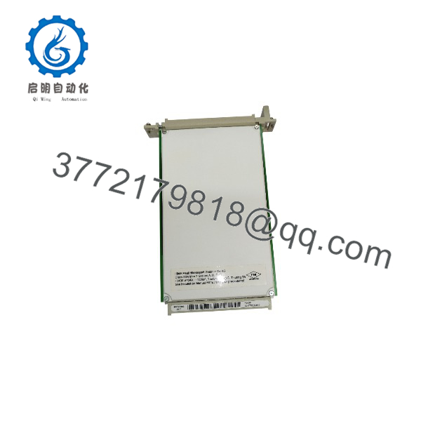
F3430
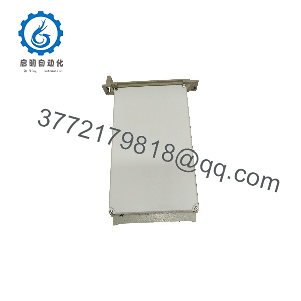
F3430
Frequently Asked Questions (FAQ)
Can the HIMA be hot-swapped under power?
No. The is a safety-related relay output module. Removing it under power can affect safety circuits and should only be performed under an approved maintenance procedure. Normal replacement requires the rack power to be isolated.
What is the main function of the HIMA ?
The provides four safety relay outputs for switching external safety circuits. It is commonly used for shutdown functions where the safety controller must isolate or disconnect field equipment.
Is the HIMA obsolete?
The belongs to the legacy HIMA H41q/H51q safety platform. Availability depends on remaining industrial spare inventory. Many facilities continue maintaining these systems because migration requires safety engineering review, validation, and planned downtime.
Can the replace the HIMA F3422 relay module?
Not directly. The and F3422 have different relay functions and electrical specifications. The is a SIL-related 4-channel relay output module rated for higher switching voltage applications. Confirm the approved spare-part list before replacement.
Will replacing the erase the HIMA safety program?
No. The safety application remains stored in the controller configuration. However, the replacement relay module must match the hardware configuration used in the approved safety application.
Why is the available below current OEM pricing?
Legacy automation spare parts are often sourced from unused inventory, discontinued stock, or tested refurbished channels. Pricing depends on condition, documentation, testing records, and remaining availability.
What should I verify before ordering an HIMA ?
Check:
- HIMA system family: H41q / H51q
- Exact model:
- Relay channel count
- Switching voltage and current
- External fuse arrangement
- Safety application requirements
A similar-looking relay module may not meet the same SIL requirements.
How should a surplus be tested before installation?
A proper inspection process should include:
- Verify OEM label and serial number.
- Inspect relay contacts, connectors, and housing condition.
- Test installation on a compatible HIMA rack.
- Verify LED and diagnostic functions.
- Simulate relay switching operation.
- Generate a functional test report.
Test photos and inspection records should be retained for safety lifecycle traceability.



