
 WhatsApp: +86 16626708626
 Email:
  Phone: +86 16626708626
Description
Key Technical Specifications
| Parameter | Value |
|---|---|
| Model Number | F7133 |
| HIMA Part Number | 984713302 |
| Manufacturer | HIMA Paul Hildebrandt GmbH |
| Product Family | HIQuad H41q / H51q safety-system accessories |
| Product Type | Four-fold 24 V DC power distribution module |
| Primary Function | Protected power distribution and fuse-status monitoring |
| Nominal Input Voltage | 24 V DC |
| Output Voltage | 24 V DC, derived from the input supply |
| Distribution Paths | 4 independent protected output channels |
| Power Conductors | L+ or EL+ distribution and L− distribution |
| Fuse Quantity | 4 miniature fuses |
| Fuse Type | Slow-blow |
| Maximum Fuse Rating | 4 A per channel |
| Module Operating Current | Approximately 60 mA at 24 V DC |
| Fuse Status Indication | One LED per fuse/channel |
| Fuse Monitoring | Evaluation logic monitors each fuse state |
| Relay Switching Time | Approximately 100 ms |
| Relay Contact Rating | 30 V DC, 4 A continuous load |
| Residual Voltage, Fuse Tripped | 0 V |
| Residual Current, Fuse Tripped | 0 mA |
| Residual Voltage, Supply Missing | Up to 3 V |
| Residual Current, Supply Missing | Less than 1 mA |
| Backplane/Terminal Outputs | Separate rear outputs for 24 V DC distribution to assigned I/O locations |
| Module Width | 4 TE |
| System Use | HIQuad H41q/H51q safety-system rack and field-circuit distribution |
| Lifecycle Status | Legacy module; limited New Surplus and tested stock availability |
The HIMA F7133 is a power distribution and fuse-monitoring module, not a 24 V DC power supply and not a safety I/O module. It takes an externally supplied 24 V DC source and divides it into four separately fused field-power paths, with LED indication and monitored relay outputs for fuse fault detection.
Product Introduction
The HIMA F7133, part number 984713302, distributes protected 24 V DC power to separate field circuits in legacy HIQuad H41q and H51q safety systems. Its four channels use individual slow-blow fuses and LED status indicators, allowing maintenance teams to identify a failed field-power branch without losing visibility of every powered circuit.
Use the F7133 where the existing safety rack requires monitored, fused L+ or EL+ and L− distribution to sensors, contact circuits, or I/O interface loads. It does not generate 24 V DC; the upstream cabinet supply must already be stable, correctly fused, grounded, and sized for the connected field loads.
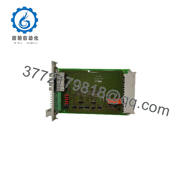
F7133
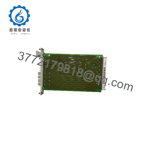
F7133
Troubleshooting Quick Reference
| Symptom | Possible Cause | Relevance to This Part | Quick Check Method | Recommendation |
|---|---|---|---|---|
| All four output branches are dead | Missing upstream 24 V DC supply, open cabinet fuse, loose L+/L− terminal, common return fault | ❌ Low until input is verified | Measure 24 V DC directly at the F7133 input terminals using a calibrated meter; check the upstream power supply, breaker, common return, and incoming fuse | Restore the input supply before replacing the F7133 |
| One channel LED is off and the associated field circuit is dead | Blown miniature fuse, shorted field cable, failed sensor or load, excessive inrush current | ❌ Usually field-side | Isolate the field branch, check fuse continuity with power removed, then inspect cable insulation and measure load resistance | Clear the external fault before installing a replacement fuse |
| Replacement fuse blows immediately | Persistent short circuit, reversed field wiring, crushed cable, failed solenoid/sensor, wrong fuse rating | ❌ Low | Keep the branch disconnected, install only the approved slow-blow fuse, then reconnect loads one at a time under authorized conditions | Do not fit a larger fuse. Find the fault with an insulation and resistance check |
| Channel LED is on but field device has no power | Open field conductor, loose terminal, failed device, broken common return, wiring landed on wrong output | ❌ Usually field wiring | Measure 24 V DC at the output and again at the field device; check both L+ and L− paths | Repair wiring or the device. The is likely healthy if output voltage is present at its terminal |
| Safety controller reports a fuse fault but LED appears normal | Intermittent fuse contact, loose fuse holder, evaluation-circuit fault, connector problem, transient load event | ✅ Medium | Review controller diagnostics, inspect fuse seating, measure voltage across the fuse under load, and gently check holder retention with power isolated | Replace the fuse and inspect holder/contact condition; replace the module only if the fault remains with known-good fuse and load |
| Fuse fault occurs only during actuator operation | Coil inrush exceeds fuse or branch capacity, damaged suppression diode, load insulation failure, water ingress | ❌ Usually external load | Measure startup current with a suitable clamp or current probe; inspect coil resistance and suppression hardware | Use the correct approved fuse and interface design. Do not oversize protection to mask inrush |
| Several channels fail after cabinet maintenance | L+ and L− wires swapped, terminal block loose, wrong fuse positions, common return omitted, connector not fully seated | ❌ Common installation error | Compare terminal numbers, wire IDs, fuse ratings, and connector position against photos and approved drawings | Do not wire from memory. Restore the documented layout before applying power |
| No fuse indication after a supply replacement | Upstream supply voltage too low, input polarity reversed, shared 0 V disconnected, wrong terminal wiring | ❌ Usually supply installation | Measure input voltage and polarity at the module; verify 24 V DC across L+ and L−, not only L+ to cabinet earth | Correct the supply and common return. Do not replace the until the input is proven |
| becomes hot | High continuous branch loading, loose terminal connection, undersized wire, high ambient temperature, internal damage | ✅ Medium | Measure voltage drop across each fuse and at terminals under load; inspect for discoloration, loose screws, and cabinet temperature | Reduce load and correct wiring resistance. Replace the module if heating continues at rated load |
| A branch has voltage but controller does not see its fuse healthy | Fuse-monitoring relay wiring fault, backplane connection issue, evaluation contact fault, project diagnostic mapping issue | ✅ Medium | Verify actual fuse condition, LED status, relay/evaluation wiring, and controller diagnostic mapping | Repair the feedback path. Replace the only after confirming the monitor circuit is defective |
| New has immediate fuse alarms | Incorrect module connection, wrong fuse type, existing field short, old terminal wiring transferred incorrectly | ✅ Medium | Compare old/new labels, inspect every branch before energization, and power branches individually where the procedure permits | Correct the field fault and confirm fuse ratings before declaring the new module defective |
| Field circuit shows residual voltage while de-energized | Ghost voltage through monitoring circuit, induced voltage, external backfeed, high-impedance meter reading | ❌ Often not a module failure | Measure with an approved low-impedance meter or test load and isolate external sources; compare with residual specifications | Trace backfeed or induced voltage. Do not replace the module based only on a high-impedance reading |
❗ Fuse warning: The uses four slow-blow miniature fuses, each with a maximum rating of 4 A. Do not fit a higher-rated fuse to stop nuisance trips. A larger fuse can turn a cable fault or failed field load into burned wiring, damaged terminals, or a cabinet fire.
❗ Fault-before-fuse warning: Always find the reason a fuse opened before replacing it. A fuse is evidence, not the root cause. In the field, the usual culprits are pinched cable, a wet junction box, a solenoid coil starting to short, or a technician landing L+ on the wrong terminal.
❗ L− warning: Check the return conductor just as carefully as L+. A healthy L+ output is useless if the shared L− path is open. This catches people constantly because they measure 24 V from L+ to cabinet earth, see a normal number, and assume the actual field circuit has a complete return.
❗ Safety-system warning: The may distribute power to safety inputs, output interface relays, or field devices inside a safety function. Do not remove fuses, bridge branches, or bypass fuse alarms to keep a process running. Follow lockout/tagout, management-of-change, and the site’s safety-system test procedure.
If troubleshooting remains unclear, contact technical support with the and 984713302 label photo, incoming 24 V DC reading, fuse ratings, LED states, fuse continuity results, field-load resistance, controller diagnostic export, and terminal-side wiring photos. Keep these checks in mind and you will save yourself most of the usual rework time.
Frequently Asked Questions
What is the HIMA used for?
The HIMA is a four-channel, fuse-monitored 24 V DC power distribution module for legacy HIQuad safety systems. It divides one 24 V DC source into four separately protected circuits and provides visual and monitored indication when a branch fuse opens.
Does the generate 24 V DC power?
No. It is not a power supply. The receives 24 V DC from an external cabinet power supply and distributes that voltage through four fused channels. If there is no voltage at the input, replacing the module will not restore field power; check the upstream power supply, breaker, fuse, wiring, and common return first.
What fuse rating should I use in an ?
Use the fuse type and value specified by the approved system design, with a maximum slow-blow fuse rating of 4 A per channel. The correct value depends on conductor size, field-device current, inrush current, required fault-clearing behavior, and safety-loop design.
Do not select a fuse only from the connected device’s normal current. A solenoid or relay can have startup current well above its holding current, while a long cable may require a lower protective rating than the load alone suggests.
Can I use the to power solenoids and relays?
It can distribute 24 V DC to properly designed field circuits, including relay or solenoid interface circuits, provided each branch stays within the approved fuse rating and the relay-contact rating of 30 V DC, 4 A continuous load. Verify coil inrush, cable length, suppression method, fuse coordination, and safety-function behavior before connecting final elements.
Can I hot-swap a fuse or the module?
Do not assume that either operation is permitted. Removing a fuse may remove power from a safety input, output, relay, or monitored circuit and can initiate a trip. Pulling the entire can affect four circuits at once. Follow the site’s approved maintenance procedure, put the process in a safe condition, isolate power where required, and document the branch wiring before intervention.
Is the obsolete?
The is linked to legacy HIMA HIQuad H41q/H51q systems, and current sourcing is generally through New Surplus or tested refurbished inventory. The HIMA downloads catalog still identifies an H41q/H51q data sheet, but exact lifecycle status and support depend on the installed system version and region. Maintain a tested spare, the correct fuse inventory, complete wiring drawings, and a migration plan for critical safety systems.
Why does the controller show a fuse fault after I replace the fuse?
The branch may still have an open return, a loose fuse holder, a bad evaluation contact, a damaged terminal, an active field short, or a diagnostic condition that has not reset under the approved logic sequence. Verify actual voltage before and after the fuse, inspect the holder, measure branch resistance with power isolated, and review controller diagnostics. Do not repeatedly cycle fuses into a suspected short.
How should a New Surplus be tested before shipment?
Start with inbound inspection and traceability: verify the and 984713302 nameplate, serial number, front connector, fuse holders, LEDs, terminals, backplane contacts, and housing. Check for corrosion, discoloration, heat damage, cracked holders, loose contacts, unauthorized rework, or missing fuse hardware.
For live testing, install the module in a compatible HIQuad test fixture or controlled power-distribution setup. Apply regulated 24 V DC to the input, use four correctly rated slow-blow test fuses, and connect controlled loads to each branch. Verify 24 V DC reaches every output under load, each LED indicates normal fuse condition, and each monitored fuse alarm operates when a test fuse is opened or a controlled fault condition is introduced.
Confirm that a tripped fuse produces 0 V and 0 mA residual output, then check that missing input supply produces no more than 3 V residual voltage and less than 1 mA residual current. Test relay/evaluation response timing near the specified 100 ms. Record supply voltage, fuse values, output current per channel, LED states, diagnostic results, test duration, and final QC sign-off. Package the module in ESD-safe material with fuse-holder protection and heavy-duty corrugated packaging. Test photos and video should be available upon request. Available specifications identify the as a 24 V DC, four-fold power-distribution module with four slow-blow fuses rated up to 4 A, individual LED indication, monitored fuse evaluation, and approximately 100 ms relay switching.



