
 WhatsApp: +86 16626708626
 Email:
  Phone: +86 16626708626
Description
3. Key Technical Specifications
| Parameter | Specification / Value |
|---|---|
| Safety Integrity Level | IEC 61508 SIL 3 |
| Nominal Input Voltage | 24 V DC (−15% / +20% tolerance) |
| Input Current Consumption | ≤ 40 mA |
| Output Contact Type | Floating Normally Open (NO) contacts in diversity |
| Maximum Switching Voltage | 250 V AC / 127 V DC (220 V DC max at lower currents) |
| Maximum Continuous Current | 4 A |
| Response / Reset Time | Approx. 8 ms / Approx. 6 ms |
| Contact Material | AgNi (Silver Nickel), hard gold-plated |
| Mechanical Lifespan | ≥ 30,000,000 cycles |
| Internal Fuse Rating | Max 4 A slow blow (Terminal 8 dedicated for fuse monitoring) |
| Mounting Configuration | 35 mm standard DIN rail or C profile |
| Operating Temperature | −25 to +60°C |
4. Product Introduction & Supply Chain Strategy
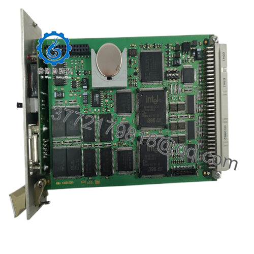
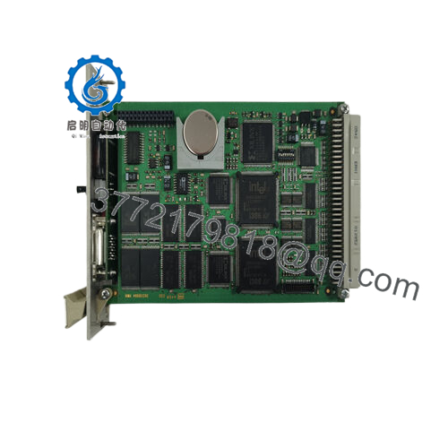
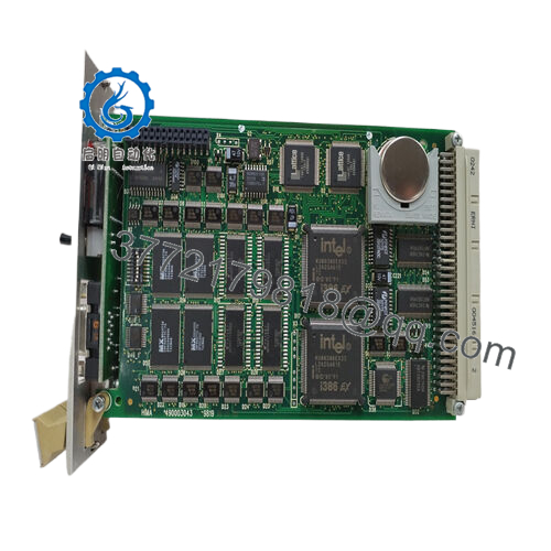
The HIMA H4135A is a high-reliability, safety-related relay module housed in a compact electronic enclosure, designed primarily for the H41q and H51q HIQuad safety systems. Operating as a critical hardware interface between safety PLC digital output cards and field-side actuators, this module provides safe electrical isolation up to SIL 3 parameters per IEC 61508. It is frequently deployed to execute final element shutdowns, such as closing fuel supply line valves in boiler systems or tripping emergency isolation block valves in petrochemical reactor loops.
From a Total Cost of Ownership (TCO) perspective, choosing a New Surplus H4135A rather than a cheap refurbished alternative is standard risk management. Relays are mechanical wear items with finite electrical switching cycles. Refurbished units often carry internal contact erosion or stress fractures in the relay coils that escape basic visual screening, leading to dangerous stiction or failure to open on demand. By maintaining a factory-sealed safety stock on-site, you prevent lead time variability and secure plant reliability, avoiding multi-million dollar outages caused by a faulty component trip.

- H4135A
5. Installation & Configuration Guide
Stage 1: Pre-Installation (Prep & Safety)
- Lock-Out/Tag-Out (LOTO): Verify that the specific 24 V DC coil loop and the associated high-voltage field contact lines are fully isolated and tagged out before working in the cabinet.
- Anti-Static Precautions: Put on a grounded ESD wrist strap to protect any adjacent digital components or terminal rails from static discharge.
Shenzhen Changxin
- Verify Internal Fuse: Check that the integrated fuse (F1, max 4 A slow-blow) is securely seated and intact prior to physical mounting.
Stage 2: Removal
- Disconnect Terminals: Safely unclip or unscrew the wiring harness connected to the front terminal layout. Take note of Terminal 8, which is isolated for active fuse monitoring.
Power Duke
- Unmount from DIN Rail: Insert a small flat-head screwdriver into the base release clip on the underside of the electronic housing.
- Pull Smoothly: Lever the housing up and outward to release it cleanly from the 35 mm DIN rail without applying stress to adjacent interface relays.
Stage 3: Installation (Clone & Seat)
- Align Housing: Position the new H4135A flat against the DIN rail, ensuring the upper track hook aligns perfectly with the rail channel.
- Snap Securely: Press down firmly on the lower edge until the spring-loaded assembly clip locks securely onto the base track.
- Wire Terminal Mapping: Terminate wires exactly as per the system engineering documents. Maintain clean separation between the low-voltage 24 V DC drive inputs and high-voltage AC contact loops.
Stage 4: Power-On & Testing
- Test the Power Bus: Apply 24 V DC to the input channel and ensure the input current does not exceed the nominal 40 mA threshold.
Power Duke
- Measure Contact Execution: Force a safety logic test from the controller and verify that the module clicks cleanly, reading zero resistance across the floating NO terminals.
- Verify Fuse Monitor Line: Check Terminal 8 under operational load to ensure your external monitoring circuit registers loop continuity correctly.
6. Firmware/Software Versions & Upgrade Notes
Engineering Architecture Note: The HIMA H4135A is an autonomous electromechanical safety component operating at the physical hardware layer.
This safety relay does not contain a programmable microprocessor, communication flash memory, or flashable system chips. Consequently, there are no software version handshakes or firmware code loads required during a part swap. It is transparent to the system’s software programming environment. When executing engineering updates or replacement schedules, verify that the physical contact material specs and current tolerances line up with the specific version code stamped on the side label to guarantee compliance with your system’s original TUV safety certificates.
7. Frequently Asked Questions (FAQ)
Q: Why is a New Surplus safety relay preferred over a refurbished component? A: Refurbished relays pose hidden risks. Arcing during previous field service can cause microscopic pitting and gold-layer erosion on the AgNi contacts. This erosion can cause contacts to weld under load, preventing a safe shutdown. A genuine New Surplus module provides a fresh mechanical lifespan with zero contact wear.
Q: What is the exact function of Terminal 8 on this module housing? A: Terminal 8 is engineered for active monitoring of the internal F1 fuse. It connects directly to the fuse trace, allowing safety systems to continuously read line health. This connection must only be linked to an externally fused voltage supply that does not exceed a 4 A slow-blow rating.
Q: Does this relay module support live hot-swapping under active operation? A: If the module is part of a non-redundant safety interlock loop, pulling it out will immediately open the contact path, causing downstream field actuators to drop out and triggering a local loop trip. Only swap this module if the target loop has been isolated or bypassed via certified plant safety override bypass keys.
Q: What are the mandatory proof-test intervals for the H4135A module? A: To maintain adherence to strict functional safety guidelines, an offline proof test verifying the positive opening of each relay contact must be conducted at least once every 5 years for SIL 3 installations. For standard SIL 2 processes, the maximum interval is 20 years.
Q: Can this module be installed directly into hazardous areas on-site? A: Yes, the H4135A can be deployed within Zone 2 hazardous environments provided it is mounted inside an approved, secondary protective cabinet rated to a minimum of IP 54. The enclosure must safely dissipate thermal loads (typically between 1 to 3 Watts per module) and feature a prominent warning label stating that work must only be carried out when the system is completely de-energized.



