
 WhatsApp: +86 16626708626
 Email:
  Phone: +86 16626708626
Description
Key Technical Specifications
| Parameter | Value |
|---|---|
| Part Number | 05701-A-0326 |
| Manufacturer | Honeywell Analytics |
| System | Honeywell System 57 / 5701 Control System |
| Module Type | Field Interface Card |
| Primary Function | Interface between sensor field wiring and Single Channel Control Card |
| Relay Outputs | None |
| Sensor Connections | Sensor 01, Sensor S, Sensor NS |
| Supply Connections | +24 V (Out/In), 0 V (Out/In) |
| Analog Output Terminals | Analog O/P (+), Analog O/P (-) |
| Remote Inputs | Remote Inhibit In, Remote Reset In |
| Ground Connections | Dedicated ground terminals |
| Compatible Rack Architecture | System 57 3U/6U sub-rack configurations |
| Control-Card Interface | Via System 57 rack/card interconnection |
| Field Wiring Access | Front-access or rear-access rack configuration |
| Relay Contacts | Not fitted on 05701-A-0326 |
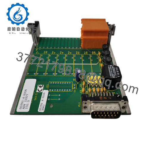
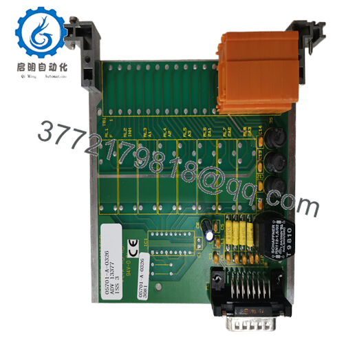
Honeywell’s System 57 documentation identifies 05701-A-0326 specifically as the Field Interface Card. It is used on channels other than the master-relay channel and provides the connection between the sensor and the associated control card; unlike the 05701-A-0327 through -0330 relay cards, it has no relays fitted.
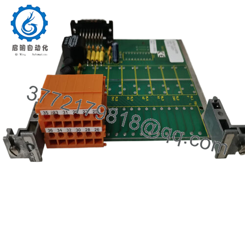
The documented rear-access terminals include sensor connections, analog output, remote inhibit/reset, +24 V, 0 V, and ground. The front-access version provides the corresponding terminal arrangement for front-wiring rack configurations.
Product Introduction
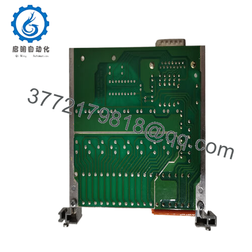
The Honeywell 05701-A-0326 is a Field Interface Card for the Honeywell System 57 / 5701 gas detection control system. It interfaces field sensor wiring with the corresponding Single Channel Control Card and provides connections for sensor signals, analog output, remote inhibit/reset, power, and ground. It is a passive interface component rather than a standalone gas detector controller.
This card is specifically intended for System 57 configurations using master-relay arrangements. Honeywell specifies it for channels other than the master and confirms that no relay contacts are fitted. The correct replacement therefore depends on the existing rack architecture, control-card type, field-wiring arrangement, and exact part-number revision.
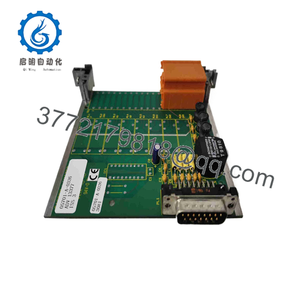
05701-A-0326
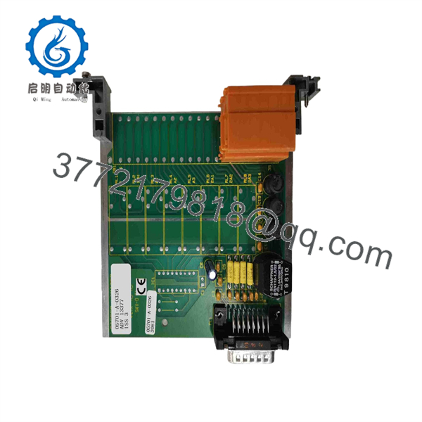
05701-A-0326
Installation & Configuration Guide
Stage 1: Pre-Installation Preparation — Allow 10–15 Minutes
⚠️ Safety First: The System 57 manual states that installation and operation require qualified personnel and that the equipment is intended for indoor use. Follow the applicable site permit, isolation, and gas-detection maintenance procedures before removing the card.
- Place the affected gas-detection channel into the approved maintenance state.
- Isolate power according to the site procedure. Do not assume the card is safe to remove merely because the channel display is inactive.
- Wear a grounded ESD wrist strap when handling the PCB.
- Photograph the existing card, terminal wiring, rack position, and cable routing.
- Record the exact part number and revision marking on the existing interface card.
- Confirm whether the rack uses front-access or rear-access field wiring. Honeywell provides different physical connection arrangements for these configurations.
- Keep the existing 05701-A-0326 available for terminal-by-terminal comparison.
Stage 2: Removing the Existing Card — Allow 5–10 Minutes
- Verify the channel and rack slot before disconnecting anything.
- Identify the field terminals associated with the card.
- Label each wire before removal.
- Photograph the terminal arrangement from multiple angles.
- Disconnect the field wiring without pulling on the conductors.
- Release the applicable rack/card retaining mechanism.
- Pull the card straight out and avoid stressing the card connectors or backplane.
- Inspect connectors for oxidation, contamination, bent contacts, or mechanical damage.
⚠️ Do not use the terminal layout of a 05701-A-0327, -0328, -0329, or -0330 as a substitute for the 05701-A-0326 wiring arrangement. Those cards provide relay functions that the 05701-A-0326 does not.
Stage 3: Installing the 05701-A-0326 — Allow 5–10 Minutes
- Confirm the replacement marking reads 05701-A-0326.
- Compare connector orientation and physical construction with the removed card.
- Confirm the card belongs in the same System 57 interface position.
- Insert the card carefully without forcing the connector.
- Reconnect the field wiring using the photographs and original wiring documentation.
- For rear-access systems, verify the documented terminal functions:
- Terminal 26: Ground
- Terminal 28: Sensor 01 Connection
- Terminal 27: Sensor S Connection
- Terminal 29: Sensor NS Connection
- Terminal 31: Analog O/P (+)
- Terminal 32: Analog O/P (-)
- Terminal 33: Remote Inhibit In
- Terminal 34: Remote Reset In
- Terminal 35: +24 V
- Terminal 36: 0 V
- Do not move terminals based solely on memory. Verify against the applicable System 57 manual and site drawings.
Stage 4: Power-On & Functional Testing — Allow 10–15 Minutes
- Perform a visual inspection before restoring power.
- Check for loose conductors, accidental shorts, and incorrect terminal placement.
- Restore rack power according to the approved commissioning procedure.
- Confirm that the associated Single Channel Control Card starts normally.
- Verify the sensor signal at the control card.
- Check the channel display and alarm status.
- Test the applicable remote inhibit/reset functions if they are wired.
- Verify the analog output circuit if the installation uses the control card’s optional analog output function.
- Perform the required gas detector calibration or functional test using the site’s approved procedure.
The 05701-A-0326 itself does not contain the gas-detection processing logic. The Single Channel Control Card processes the sensor signal, displays the reading, evaluates alarm limits, and handles the associated alarm functions.
⚠️ Important: Do not treat a successful power-up as proof that the gas-detection channel is operational. Complete the required sensor, alarm, and signal-loop checks before returning the channel to service.
Frequently Asked Questions (FAQ)
Can the Honeywell 05701-A-0326 be used as a standalone gas detector controller?
No. The 05701-A-0326 is a Field Interface Card, not the complete control electronics. It works with a System 57 Single Channel Control Card and the associated sensor drive arrangement.
Does the 05701-A-0326 have relay outputs?
No. Honeywell explicitly identifies this version as a Field Interface Card with no relays fitted. If the application requires A1/A2/fault relay contacts, verify whether a different System 57 relay-card part number is required.
What is the difference between 05701-A-0326 and 05701-A-0327?
The 05701-A-0326 provides the field interface between the sensor and control card without relays. The 05701-A-0327 performs the same basic interface function but adds relay contacts for A1, A2, and fault outputs. They should not be treated as interchangeable without checking the system design.
Is the 05701-A-0326 compatible with every System 57 channel?
Not automatically. Honeywell specifies the card for systems with master relays and says it is used on channels other than the master. Confirm the existing rack configuration, associated control card, field wiring, and applicable manual revision before replacement.
Does replacing this card change the gas detector configuration?
The Field Interface Card itself is primarily an interface component. The System 57 Single Channel Control Card contains the software configuration in EEPROM and performs the channel control, display, alarm, and self-validation functions. Therefore, replacement of the interface card should not be treated as replacement of the configured control card.
Is Honeywell 05701-A-0326 an obsolete or current product?
It is a legacy System 57 component, and current stock should be verified on a unit-by-unit basis. Honeywell’s available System 57 operating documentation identifies the 05701-A-0326 as the Field Interface Card. For procurement, confirm the exact part number, revision, physical condition, and test status rather than relying only on a generic “new” description.
What should I verify before purchasing a replacement?
At minimum, verify 05701-A-0326, the System 57/5701 rack configuration, front- or rear-access wiring, the associated Single Channel Control Card, terminal arrangement, and the condition/revision marking of the replacement. Honeywell specifically cautions users to ensure that the manual and equipment details match the exact equipment being installed.



