
 WhatsApp: +86 16626708626
 Email:
  Phone: +86 16626708626
Description
Key Technical Specifications
| Parameter | Value |
|---|---|
| Part Number | 51304485-100 |
| IOP Model | MU-PDIX02 |
| Manufacturer | Honeywell |
| Product Type | Digital Input IOP |
| System | Honeywell TDC 3000 / Process Manager |
| I/O Type | Digital Input |
| Input Channels | 32 |
| Input Configuration | Contact inputs with isolated common return |
| 24 VDC FTA Input Range | 20–30 VDC |
| 120 VAC FTA Input Range | 90–132 VAC RMS |
| 240 VAC FTA Input Range | 180–264 VAC RMS |
| Redundancy | Not supported |
| Conformal Coating | Non-conformal coated |
| Compliance | CE-compliant |
| Compatible FTA Families | MU-TDIA12, MU-TDIA22, MU-TDIA52, MU-TDIA62, MU-TDID12, MU-TDID52 and corresponding MC-series FTAs |
| Alternate Part Number | 51304485100 |
Honeywell’s Experion Control Hardware Planning Guide identifies MU-PDIX02 as the digital-input IOP associated with 51304485-100 and lists it as the CE-compliant, non-conformally coated version.
The 32-channel capacity and the three FTA-dependent input ranges are independently documented by Honeywell DCS hardware specialists. The IOP itself interfaces with the compatible FTA; therefore, the field input voltage must be checked at the FTA level rather than assumed from the IOP part number alone.
Product Introduction
The Honeywell 51304485-100 MU-PDIX02 is a 32-channel digital input IOP used with Honeywell process-control hardware. It accepts contact inputs through compatible field termination assemblies (FTAs), with 24 VDC, 120 VAC, and 240 VAC input configurations available through the appropriate FTA.
This distinction matters during replacement: 51304485-100 is the IOP card, not the field termination assembly. The existing FTA must be identified before ordering. Honeywell’s hardware documentation also specifies that this version is CE-compliant and non-conformally coated.
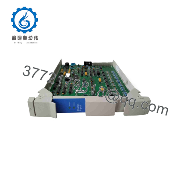
51304485-100
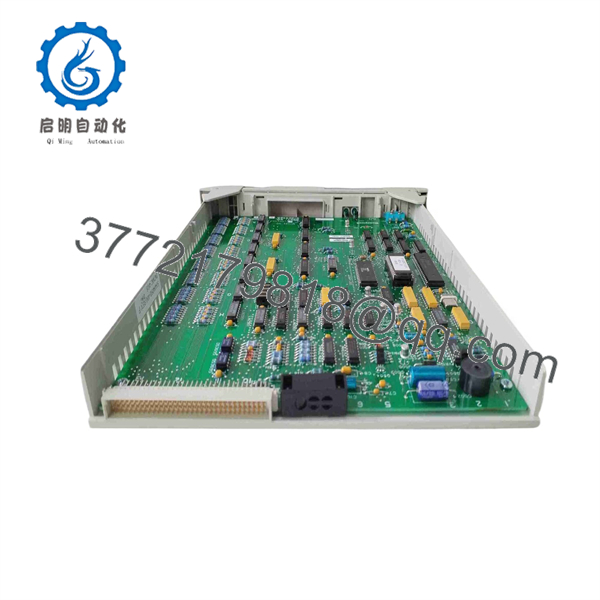
51304485-100
Installation & Configuration Guide
Stage 1: Pre-Installation Preparation — Approx. 10–15 Minutes
⚠️ Safety First
- Notify operations and obtain authorization for the I/O maintenance window.
- Place the affected process in its approved safe state.
- Apply the site’s lockout/tagout procedure as required.
- Remove power from the affected I/O module before removing the card.
- Wait for the applicable system discharge period.
- Verify the module is de-energized before handling the PCB.
Honeywell’s handling guidance specifically warns that the card must be protected against ESD and that power must be off before removing or inserting the card.
Tools Required
- Grounded ESD wrist strap
- Conductive ESD work surface
- Digital multimeter
- Appropriate card-retaining hardware tool
- Wire labels
- Smartphone/camera for documentation
Data Backup
- Record 51304485-100 and MU-PDIX02 from the existing card.
- Record the card’s hardware revision if marked.
- Photograph the card front and rear.
- Photograph the FTA and its terminal wiring.
- Record the FTA model number.
- Record the affected I/O points and controller configuration.
- Document whether the FTA is configured for 24 VDC, 120 VAC, or 240 VAC inputs.
⚠️ Do not order the IOP and FTA as though they are the same component. The 51304485-100 is the IOP; the field termination assembly determines the field-side input arrangement.
Stage 2: Removing the Old Module — Approx. 5 Minutes
- Confirm that the affected module is de-energized.
- Put on the grounded ESD wrist strap.
- Verify the wrist strap is connected to the approved chassis/ground point.
- Remove the card-retaining mechanism.
- Handle the PCB only by its edges.
- Withdraw the IOP straight from its slot.
- Do not touch PCB traces, connector contacts, or components.
- Place the removed card directly into an approved conductive ESD bag.
- Inspect the card slot and connector for contamination or mechanical damage.
Honeywell’s published handling instructions specifically state that cards should remain in their protective bags until needed and should not be touched without appropriate ESD protection.
⚠️ Keep the original card until the replacement has completed functional testing.
Stage 3: Installing the New Module — Approx. 5–10 Minutes
- Verify the replacement is marked 51304485-100 / MU-PDIX02.
- Compare the hardware revision with the original.
- Confirm that the replacement is the required non-conformally coated version.
- Confirm the installed FTA is compatible.
- Check the FTA model against the Honeywell configuration documentation.
- Remove the replacement card from its ESD packaging only after grounding yourself and the work area.
- Hold the card by its edges.
- Align the card with the correct slot.
- Insert it without forcing the connector.
- Secure the card using the original retaining mechanism.
- Verify that the card is fully seated.
Self-Checklist
- 51304485-100 verified
- MU-PDIX02 verified
- Hardware revision checked
- FTA model identified
- Field voltage confirmed
- ESD precautions followed
- Card fully seated
- Retaining mechanism secured
Stage 4: Power-On & Testing — Approx. 10–20 Minutes
Pre-Power Check
- Inspect the card connector for foreign material.
- Verify that no loose wiring exists around the I/O rack.
- Confirm the correct FTA is connected.
- Verify the field voltage against the system documentation.
- Confirm all cabinet covers and protective barriers are correctly positioned.
Power-On Steps
- Restore power according to the approved Honeywell procedure.
- Observe the IOP status indications.
- Check the TDC 3000/Process Manager diagnostics.
- Verify that the IOP is recognized by the system.
- Check the configured 32 input points.
- Apply a known field input to selected channels.
- Confirm the corresponding digital status changes in the control system.
- Test representative channels across the module.
- Verify alarm and interlock states where applicable.
- Return the affected process to normal operation only after the I/O test passes.
⚠️ If the card is recognized but input states are wrong, check the FTA and field voltage before replacing the IOP again. The same IOP can be used with different FTA/input-voltage configurations, so a mismatch at the field termination level can produce misleading symptoms.
Technical Pitfalls
❗ FTA voltage mismatch: The 51304485-100 itself does not mean “24 VDC input.” The compatible FTA determines whether the field circuit is 20–30 VDC, 90–132 VAC RMS, or 180–264 VAC RMS.
❗ IOP vs. FTA confusion: This is a common procurement mistake. 51304485-100 is the MU- digital-input IOP; it is not the FTA.
❗ Redundancy assumption: Honeywell hardware listings specify that the 51304485-100 IOP does not support redundancy. Do not design a redundant I/O architecture around this card without a documented compatible architecture.
❗ Conformal-coating mismatch: Honeywell’s planning documentation identifies 51304485-100 as the non-conformally coated CE-compliant MU- version. A coated replacement should not be assumed equivalent without checking the equipment requirements.
❗ ESD damage: These cards can be damaged during handling. Honeywell specifically requires grounded wrist-strap procedures and conductive packaging for card handling.
Frequently Asked Questions (FAQ)
Q1. What is Honeywell 51304485-100?
51304485-100 is the Honeywell MU- Digital Input IOP, providing 32 digital input channels for Honeywell process-control systems. Honeywell’s hardware planning documentation maps MU- directly to part number 51304485-100.
Q2. Is 51304485-100 a 24 VDC digital input card?
Not exactly. The IOP works with different compatible FTAs. Honeywell system documentation identifies configurations for 20–30 VDC, 90–132 VAC RMS, and 180–264 VAC RMS, depending on the FTA installed.
Q3. How many digital inputs does 51304485-100 have?
It has 32 digital input channels. The inputs share an isolated common return according to the published hardware specification.
Q4. Can I replace 51304485-100 with 51304485-150?
Do not make that substitution without checking the hardware documentation. The 51304485-150 is identified as a conformally coated version of the digital-input IOP, while 51304485-100 is the non-conformally coated version. The coating requirement is part of the hardware specification, not merely a cosmetic difference.
Q5. Does 51304485-100 support redundant operation?
The available hardware specification states redundancy is not supported for this IOP. If the application requires redundant I/O, verify the system architecture and approved Honeywell hardware before ordering.
Q6. Is 51304485-100 obsolete?
The part belongs to Honeywell’s legacy TDC 3000 / Process Manager I/O hardware family. Honeywell’s historical hardware planning documentation identifies 51304485-100 as the CE-compliant MU- part. Current market availability varies: some industrial suppliers list it in stock, while others list it as unavailable.
For a production-critical system, treat it as a legacy spare and verify lifecycle status, firmware/hardware revision, FTA compatibility, and actual stock condition before placing the order.
Q7. Will replacing 51304485-100 erase the I/O configuration?
The IOP is an I/O processing card rather than the primary controller database. However, do not treat replacement as a blind plug-in operation. Record the configured channels and associated FTA before removal, then verify all 32 points after the replacement is recognized by the control system.
Q8. What should I specify when purchasing 51304485-100?
Specify the complete Honeywell 51304485-100 / MU- part number, required condition, hardware revision if known, and the associated FTA model. For critical DCS applications, request photographs of the actual card label and PCB revision. This prevents a supplier from sending a visually similar Honeywell I/O card with a different part number or coating configuration.



