
 WhatsApp: +86 16626708626
 Email:
  Phone: +86 16626708626
Description
Key Technical Specifications
| Parameter | Specification Value |
| Part Number | FC-FANWR-24R |
| Operating Voltage | 24 V DC nominal (18 to 30 V DC working range) |
| Current Consumption | 0.60 A total nominal @ 24 V DC |
| Cooling Architecture | Dual brushless DC fans with individual speed monitoring |
| Alarm Interface | Integrated relay contact / tachometer status output to Safety Manager |
| Airflow Capacity | 180 CFM combined nominal forced-air cooling |
| Operating Temperature | −10 to +70°C (14 to 158°F) |
| Enclosure Rating | 19-inch rack-mountable or chassis sub-rack tray mount |
| Field Connection | Plug-in screw terminal block for power and alarm telemetry |
| MTBF | >100,000 continuous operating hours @ 40°C |
Product Introduction & Supply Chain Strategy
The Honeywell FC-FANWR-24R is a 24 V DC redundant cooling fan assembly engineered specifically for Honeywell Safety Manager and Fail Safe Control (FSC) safety instrumented system (SIS) cabinets. It maintains positive airflow across critical CPU modules, high-density I/O cards, and power supplies to prevent thermal throttling and component overheating in process safety racks.
Maintaining an FC-FANWR-24R as New Surplus is a mandatory buffer strategy for critical process safety systems. A failed fan tray leads to elevated cabinet temperatures, triggering over-temperature alarms or emergency safety trips across burner management systems (BMS) and emergency shutdown (ESD) loops. Sourcing New Surplus guarantees fresh, factory-lubricated dual ball bearings and unaged monitor electronics—eliminating the severe risk of bearing lockups associated with cheap refurbished cooling hardware.
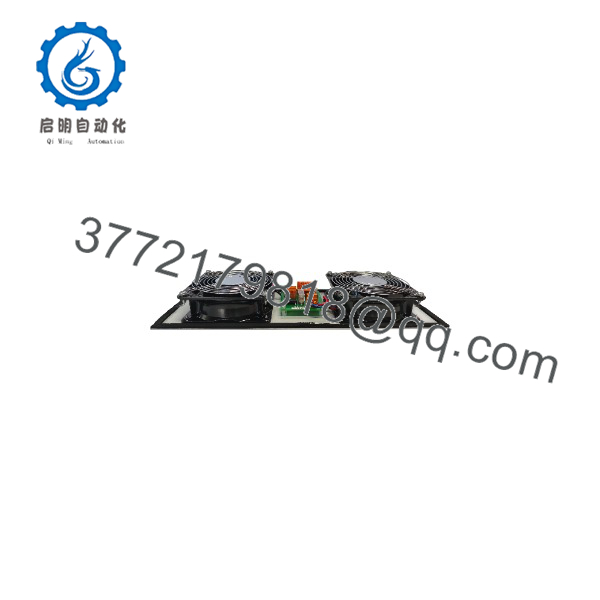
FC-FANWR-24R
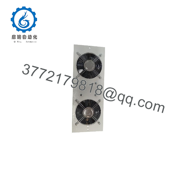
FC-FANWR-24R
Installation & Configuration Guide
Stage 1: Pre-Installation (Prep & Safety)
- Verify cabinet thermal alarms are monitored by operators on the Experion PKS / Safety Manager HMI.
- Put on a grounded ESD wrist strap before connecting power or signaling harnesses.
- Check the 24 V DC auxiliary power feed terminal on the rack for correct voltage (24.0 V DC ± 10%).
- Inspect the fan tray housing for transit damage and confirm fan blades rotate freely by hand.
Stage 2: Removal
- Unplug the 24 V DC power connector and alarm signaling harness from the front terminal block of the active fan tray.
- Unfasten the captive mounting thumbscrews on the left and right sides of the FC-FANWR-24R chassis.
- Slide the fan assembly straight out of the 19-inch sub-rack slot.
Stage 3: Installation (Clone & Seat)
- Align the new FC-FANWR-24R tray with the cabinet chassis guide rails.
- Slide the assembly smoothly into the slot until the front flange rests flush against the frame.
- Tighten the captive mounting screws to secure the tray and establish frame ground bonding.
- Reattach the 24 V DC supply plug and fan status alarm harness to the integrated terminal block.
Stage 4: Power-On & Testing
- Restore power to the 24 V DC supply loop.
- Verify both brushless fans spin immediately up to full operational RPM.
- Confirm that the fan status LED indicators turn green and that the thermal alarm point clears on the Safety Manager diagnostic display.
Firmware/Software Versions & Upgrade Notes
- System Integration: Hardware-level cooling sub-assembly requiring no internal software or firmware flashing.
- Diagnostic Monitoring: Interfaces directly with Safety Manager system diagnostic blocks (SDU/Safety Builder) via dry-contact fault feedback.
- Replacement Warning: Never replace an FC-FANWR-24R with standard commercial 24V computer fans. Non-OEM fan trays lack the precise tachometer sensing and noise immunity required by Safety Manager diagnostic logic, which can trigger nuisance hardware fault alarms.
Frequently Asked Questions (FAQ)
What happens if one of the fans on the FC- fails during operation?
The FC- features dual-fan redundancy. If a single fan experiences bearing drag or electrical failure, the remaining fan continues providing sufficient emergency airflow while the integrated monitoring PCB trips a dry-contact alarm to alert operators via the DCS diagnostic interface.
How can I confirm this FC- unit is genuine New Surplus?
Our New Surplus units come from verified OEM spare stocks and project overruns. They arrive in factory packaging with pristine aluminum fan guards, untarnished terminal blocks, zero dust on the fan impellers, and verified Honeywell serial number tags.
Can I replace the FC- fan tray while the Safety Manager is online?
Yes. The FC- fan tray is designed for hot-swap maintenance. However, you should complete the hardware exchange within 5 to 10 minutes to prevent heat buildup inside the active Safety Manager rack during the swap.
What is the difference between the FC- and non-“R” fan tray models?
The “R” designation indicates built-in fan tachometer monitoring and redundancy logic on the central PCB assembly, allowing the Safety Manager system to detect individual fan failures before total thermal shutdown occurs.
What warranty covers this New Surplus fan tray assembly?
We back every New Surplus Honeywell FC- fan assembly with a comprehensive 1-year replacement warranty. If a fan bearing fails or the monitor board exhibits fault conditions within 12 months, we replace the tray directly from our stock.



