
 WhatsApp: +86 16626708626
 Email:
  Phone: +86 16626708626
Description
Key Technical Specifications
| Parameter | Specification |
| Model Part Number | FC-QPP-0002 |
| System Compatibility | Honeywell Safety Manager (Backward compatible with QPP-0001, R121+ firmware) |
| Operating Architecture | Dual synchronous processors with hardware data comparators (>99% diagnostic coverage) |
| Safety Level Certification | SIL3 applications (1oo2D non-redundant, 2oo4D redundant configuration) |
| Input Supply Voltage | 24 V DC (−15% / +30%) and 5 V DC (±5%) backplane power |
| On-Board Memory | 2 × 2 MB Flash (System/App), 2 × 256 KB SRAM (Battery-backed), 2 × 512 KB SRAM (Comm Link) |
| Emergency Shutdown (SD) Input | 24 V DC galvanically isolated input (De-energizes watchdog outputs directly) |
| User Interface & Controls | 8-digit diagnostic status display, Up/Down scroll buttons, 3-position Key Switch (RUN/IDLE/STOP) |
| Operating Temperature | −5°C to +70°C (External rack ambient) |
| Physical Dimensions (H x W x D) | 176 × 88.5 × 212 mm (6.93 × 3.48 × 8.35 inches) |
| Unit Weight | 1.30 kg (2.87 lbs) |
Product Introduction & Supply Chain Strategy
The Honeywell FC-QPP-0002 is the second-generation Quad Processor Pack at the core of the Honeywell Safety Manager system. Operating as the primary execution engine, it reads field I/O signals, processes functional logic diagrams (FLDs), and drives safety outputs with hardware-level data comparison to meet strict SIL3 functional safety requirements.
From a supply chain perspective, sourcing this module as New Surplus provides a vital risk-mitigation strategy for mature process safety installations. Refurbished safety modules carry unquantifiable risks of latent component fatigue in diagnostic comparators or memory cells, which can trigger nuisance trips or catastrophic fail-to-danger scenarios. Procuring factory-fresh, genuine surplus inventory eliminates second-hand wear, secures a 10-to-15 year operating lifespan, and drastically lowers the Total Cost of Ownership (TCO) compared to unplanned plant downtime.
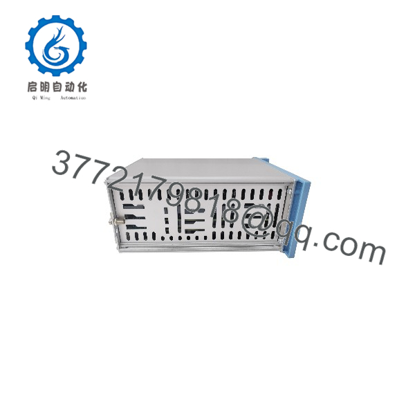
FC-QPP-0002
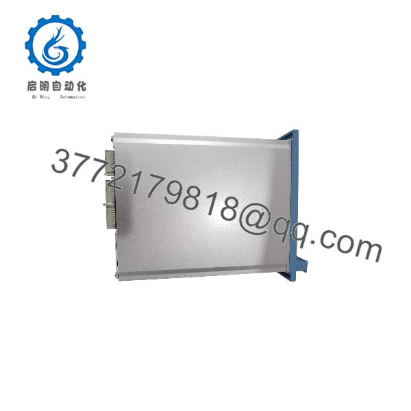
FC-QPP-0002
Installation & Configuration Guide
Stage 1: Pre-Installation (Prep & Safety)
- Execute full Lock-Out/Tag-Out (LOTO) procedures on the controller rack branch power.
- Put on an anti-static wrist strap connected to cabinet earth ground to prevent Electrostatic Discharge (ESD) damage to backplane traces.
- Record the physical node address and document software project backups.
- Inspect the target chassis slot (CPCHAS-0001 or CPCHAS-0002) for debris or pin bending.
Stage 2: Module Removal
- Turn the front panel Key Switch on the active processor module to the STOP position. This de-energizes the watchdog outputs and halts process execution safely.
- Loosen the quarter-turn locking fastener at the bottom of the front panel.
- Gently pull the module handles straight out along the chassis guide rails to avoid placing strain on backplane connectors.
Stage 3: Installation & Seating
- Inspect backplane connectors on the new FC-QPP-0002 unit to confirm zero pin alignment issues.
- Align the module card edges with the card guide rails in the designated slot.
- Slide the module firmly into the chassis until the rear multi-pin connector seats completely into the backplane socket.
- Tighten the quarter-turn fastener to lock the module in place.
Stage 4: Power-On & Testing
- Verify the 24 V DC power bus voltage rail stays within the −15% to +30% tolerance window.
- Rotate the Processor Status Key Switch from STOP to IDLE.
- Observe the 8-digit front panel display during self-test routines (displaying messages like
PowerUp,Sync, orCPready). - Turn the key switch to RUN to initiate execution of the Controller File or synchronize with the secondary redundant module.
Firmware/Software Versions & Upgrade Notes
- Recommended Base Release: Honeywell Safety Manager Release R121 or higher is required for seamless drop-in replacement when swapping older QPP-0001 modules for the enhanced FC-QPP-0002.
- Firmware Mismatch Risks: Major software revision steps can lead to communication link timeouts or FLD execution halts. Always confirm that the system software build in the Safety Builder utility matches the target processor build version.
- Hot-Swap Restrictions: The FC-QPP-0002 should only be inserted or extracted when its local key switch is set to the STOP position. Never extract an active processor while in the RUN state on a non-redundant system.
- Dual Processor Synchronization: In redundant 2oo4D configurations, the two internal microprocessors automatically execute a hardware re-synchronization routine after a project download completes.
Frequently Asked Questions (FAQ)
Q: How can you confirm this FC-QPP-0002 module is Brand New Surplus and not refurbished?
This unit is sourced directly from verified OEM overstock inventory. It features original factory anti-static packaging, intact factory seals, pristine un-sunk backplane connector pins, and zero soldering modifications. Every unit undergoes strict inbound ESD verification and serial number tracking.
Q: Is the FC- directly compatible with older QPP-0001 hardware?
Yes. The FC- is designed as an enhanced, backward-compatible replacement for the QPP-0001 processor pack, provided your Honeywell Safety Manager framework runs firmware version R121 or higher.
Q: Why is New Surplus priced higher than refurbished modules on second-hand markets?
A refurbished unit carries hidden component aging—such as dried-out electrolytic capacitors or micro-fractured solder joints—that can trigger process shutdowns costing tens of thousands of dollars per hour. New Surplus offers OEM-grade reliability, extended operating lifespan, and predictable performance, protecting your facility against costly downtime events.
Q: What happens if the Emergency Shutdown (SD) input is activated?
The 24 V DC SD input is a hardware-isolated circuit. Dropping signal voltage on this loop immediately de-energizes the watchdog outputs independently of processor execution, placing system outputs into their fail-safe state.
Q: Does replacing this module require downloading the application program again?
If replacing a single failed unit in a redundant Control Processor pair, the new module synchronizes and copies the application logic across the redundant comm link. In non-redundant systems, the application file must be reloaded via Safety Builder software while the processor key is set to the IDLE position.



