
 WhatsApp: +86 16626708626
 Email:
  Phone: +86 16626708626
Description
Key Technical Specifications
| Parameter | Value |
|---|---|
| Manufacturer | Honeywell |
| Full Model | FS-SDO-0824 |
| Product Family | Safety Manager |
| Product Type | Safe digital output module |
| Coating Version | FS type: non-conformal-coated module |
| Output Channels | 8 |
| Output Configuration | 24 V DC solid-state source outputs |
| Per-Channel Maximum Current | 550 mA maximum; limited to 350 mA at 70 °C |
| Supported Load Types | Resistive loads, such as lamps and relays; inductive loads, such as solenoids |
| Maximum Load per Channel | 13 W at 24 V DC |
| Maximum Lamp Load | 120 mA / 2.9 W |
| Maximum Load Capacitance | 1 µF |
| Output Voltage Drop | Less than 2.0 V DC at 500 mA |
| Off-State Leakage Current | Less than 0.1 mA |
| Output Protection | Short-circuit proof solid-state outputs |
| Watchdog Input Current | 8 mA |
| Internal 5 V DC Consumption | 25 mA |
| Internal 24 V DC Consumption | 25 mA |
| External 24 V DC Consumption | 70 mA without output load |
| Mechanical Format | 4 TE × 3 HE, equivalent to 4 HP × 3U |
| Key Coding | Module holes A9 and C9; chassis large pins A9 and C9 |
| Approvals | CE, TÜV, UL, CSA, FM |
Honeywell’s Safety Manager hardware reference identifies FS-SDO-0824 as an eight-channel, 24 V DC safe solid-state source-output module rated at 550 mA per channel and suitable for loads up to 13 W. It also specifies output derating to 350 mA at 70 °C, key coding A9/C9, and the FS version as non-conformal-coated.
Product Introduction
The Honeywell FS-SDO-0824 is an eight-channel safe digital output module for the Honeywell Safety Manager system. It provides 24 V DC solid-state source outputs to energize and de-energize safety-related field devices, including interposing relays, solenoid valves, annunciators, shutdown circuits, and other approved 24 V DC loads.
This is a Safety Instrumented System component, not a standard PLC output card. The FS-SDO-0824 uses short-circuit-protected outputs and must be matched to the Safety Manager chassis, external 24 V DC supply, output load, field wiring, keying arrangement, and approved safety application. The FS version is non-conformal-coated; do not assume it is interchangeable with FC-SDO-0824 in corrosive or high-humidity service.
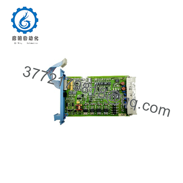
FS-SDO-0824
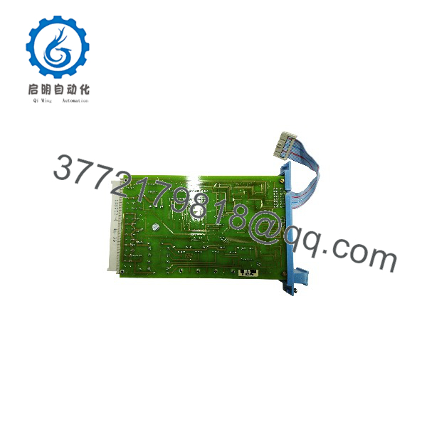
FS-SDO-0824
Troubleshooting Quick Reference
| Symptom | Possible Cause | Relevance to This Part | Quick Check Method | Recommendation |
|---|---|---|---|---|
| No output channels energize | Missing external 24 V DC, Safety Manager power fault, module not recognized, watchdog or logic state preventing output | ✅ Medium to high | Measure external 24 V DC at the module field-power terminals per the approved drawing; inspect Safety Manager diagnostics and chassis/module status | Confirm external supply, module seating, system diagnostics, and application state before replacing the module |
| One output does not energize | Open field fuse, broken wire, failed load, short-circuit-protected channel, application logic not commanding output | ✅ Medium | Command the output only under approved testing conditions; measure output voltage at the module terminal and load terminal; check the load coil resistance | Prove logic command, wiring, and load condition before replacing FS-SDO-0824 |
| Output LED indicates ON but field device remains de-energized | Open circuit, loose terminal, blown interposing relay, failed solenoid coil, incorrect 0 V return | ❌ Usually low | Measure 24 V DC at the field device; verify return path and terminal torque; check relay/solenoid coil resistance | Repair field wiring or load before replacing the output module |
| Output repeatedly cycles or turns off under load | Load current exceeds channel rating, short circuit, capacitive inrush, thermal derating, unstable 24 V DC supply | ✅ High | Measure steady-state and inrush current with an appropriate DC clamp meter; compare to 550 mA limit and 350 mA-at-70 °C limit; inspect cabinet temperature | Reduce load, add an approved interposing relay, or correct the short circuit before replacing the module |
| Output voltage is lower than expected | Excessive load current, supply sag, high-resistance terminal, output voltage drop, wiring resistance | ✅ Medium | Measure voltage at the module output and field device while energized; check for more than expected wiring drop; confirm 24 V DC supply under load | Correct supply or wiring loss. Remember the module may drop less than 2.0 V DC at 500 mA |
| Output remains energized when commanded OFF | Field wiring backfeed, external relay contact wiring error, welded interposing relay, leakage measurement method, module fault | ✅ Medium | Remove the field load under approved procedure; measure output-to-0 V voltage and current; inspect for external backfeed from another supply | Eliminate backfeed and relay faults before diagnosing the module |
| Module reports channel fault after connecting a solenoid | Coil short, wrong coil voltage, missing suppression, wiring fault, inrush beyond output capability | ✅ High | Isolate power; measure coil resistance; verify it is a 24 V DC coil; inspect flyback suppression according to approved drawing | Correct the load circuit and confirm suppression method before resetting or replacing the module |
| Replacement module is rejected or will not seat | Wrong slot, chassis keying mismatch, damaged backplane, incorrect module type | ✅ High | Verify slot assignment and key positions A9/C9; inspect module and chassis connector pins with power isolated | Use only the approved Safety Manager slot and correctly keyed module |
| Safety function does not behave as expected after replacement | Wrong configuration, unvalidated safety logic, wrong channel mapping, untested proof-test procedure | ✅ High | Compare approved Safety Manager configuration, I/O mapping, cause-and-effect chart, and test records; conduct the authorized functional test | Stop and use the site’s management-of-change and safety-validation procedure before returning to service |
Field warning: A safety output does not prove the module is bad merely because a valve or relay did not move. Most field faults are a missing external 24 V DC supply, open fuse, failed coil, poor 0 V return, or a logic permissive that correctly blocks the output.
❗ Do not jumper a Safety Manager output to force a shutdown valve, relay, or trip circuit. That bypass can defeat the designed safety function, damage the solid-state output, and invalidate the safety test. Use the approved proof-test and bypass-management procedure only.
If diagnosis remains unresolved, contact qualified safety-system support with the complete FS- label, Safety Manager diagnostic screen captures, chassis and slot details, channel number, field wiring drawing, 24 V DC measurements under load, load current, and approved cause-and-effect documentation.
Frequently Asked Questions (FAQ)
What is Honeywell FS- used for?
The FS- is a Honeywell Safety Manager safe digital output module. It provides eight 24 V DC source outputs for controlling safety-related field loads, including relays, solenoids, alarms, and shutdown interfaces. Each channel is short-circuit protected and rated up to 550 mA, subject to environmental derating.
Is FS- a standard PLC output module?
No. It belongs to the Honeywell Safety Manager safety system and should be handled as a Safety Instrumented System component. Replacement, configuration changes, wiring changes, and testing must follow the site’s approved safety lifecycle, management-of-change, proof-test, and functional-validation procedures.
What is the difference between FS- and FC-?
The output function and core electrical specifications are associated with the module family, but the coating designation differs: FS-type modules are non-conformal-coated, while FC-type modules are conformal-coated. The coating choice matters in installations exposed to humidity, condensation, corrosive atmosphere, or contaminants. Confirm the exact installed model and environmental requirement before substitution.
Can I connect a 24 V DC solenoid directly to one output?
Only if its normal and inrush current stay within the output limits, its electrical behavior is compatible with the module, and the approved system design permits direct connection. The maximum channel current is 550 mA, but Honeywell specifies a 350 mA limit at 70 °C. Consider coil inrush, cabinet temperature, wiring voltage drop, suppression requirements, and the 13 W maximum load rating before direct connection.
Why does the output show ON but my solenoid valve does not actuate?
Check the field circuit before replacing the module. Measure voltage at the output terminal and then directly across the solenoid coil while commanded ON. Inspect the field fuse, wiring, 0 V return, coil resistance, connector condition, and supply voltage. Also confirm the solenoid is a 24 V DC model. An open coil or missing return can produce this symptom with a healthy output card.
Can I hot-swap FS-?
Do not assume hot swapping is permitted. Any removal of a safety output module can change the process’s safe state, trip equipment, inhibit a safety function, or create a demand on redundant protection. Follow the site’s Safety Manager maintenance procedure, process-hazard review, bypass authorization, lockout/tagout requirements, and post-maintenance proof test before removing or installing the module.
Why must I consider temperature when sizing the output load?
The module’s available per-channel current decreases at higher temperature. Although the maximum output current is 550 mA, Honeywell specifies a 350 mA limit at 70 °C. A coil that operates normally in a cool panel can overload or create nuisance trips in a hot cabinet. Size the output circuit for the actual enclosure temperature, not only the room temperature.
What testing should a supplier perform on a surplus FS-?
Request label and part-number verification, inspection for corrosion, damaged connectors, rework, or discoloration, controlled power-up in compatible Safety Manager hardware, and channel-level output testing with suitable 24 V DC loads. The seller can verify electronic operation, but that does not validate your safety function. Your site must perform approved configuration checks, loop checks, cause-and-effect verification, and proof testing after installation.



