
 WhatsApp: +86 16626708626
 Email:
  Phone: +86 16626708626
Description
Key Technical Specifications
| Parameter | Specification / Value |
| Manufacturer | Honeywell Safety Management Systems |
| Part Number | FTA-544 |
| Alternative Part ID | 51199929-200 / FTA544 / 550544-001 |
| System Compatibility | Honeywell Safety Manager / Fail Safe Control (FSC) Systems |
| I/O Module Compatibility | Safe Analog Input Modules (e.g., SAI-1620MA, FS-SAI-1620MA) |
| Field Wiring Connection | High-density compression screw terminal blocks |
| System Cable Connection | Multi-pin system ribbon connector for I/O rack interface |
| Channel Capacity | Supports up to 16 analog loop field connections |
| Isolation Class | Galvanic isolation per channel pair |
| Mounting Style | Standard TS35 DIN rail or panel backplate mounting |
| Operating Temperature | −10°C to +60°C (14°F to 140°F) |
| Storage Temperature | −40°C to +85°C (−40°F to 185°F) |
| Dimensions (W × H × D) | 180 mm × 125 mm × 65 mm (7.1 in × 4.9 in × 2.6 in) |
| Weight | 0.45 kg (0.99 lbs) |
Product Introduction & Supply Chain Strategy
The Honeywell FTA-544 Field Termination Assembly serves as the essential physical bridge between field instrument wiring and Honeywell Safety Manager or Fail Safe Control (FSC) analog input processing modules. Designed for high-integrity Safety Instrumented Systems (SIS), the FTA-544 routes field signal wires from pressure transmitters, flow meters, and level sensors into structured, ribbon-cable system interconnects. Its rugged circuit board construction incorporates onboard surge suppression pads and test points to simplify loop calibration and signal verification without disturbing field wiring.
Securing a New Surplus FTA-544 unit makes strategic economic and operational sense for plants maintaining legacy Honeywell DCS and safety controls. Because these field termination boards are no longer actively produced by the OEM, acquiring genuine New Surplus stock protects your facility against sudden, localized channel outages. Refurbished or pulled termination boards frequently exhibit thermal stress around terminal solder joints, corroded connector pins, or stripped screw terminals caused by repeated field maintenance. A failing field termination board can introduce resistance variations into 4-20mA loops, leading to false safety trips or erroneous sensor readings. Installing a factory-sealed New Surplus FTA-544 ensures pristine contact resistance, maintains loop accuracy, and prevents unplanned downtime that can cost tens of thousands of dollars per hour.
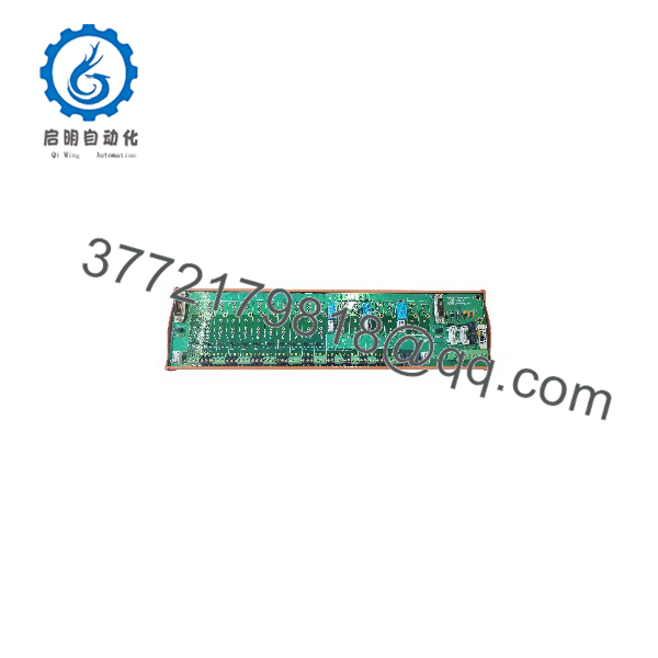
FTA-544
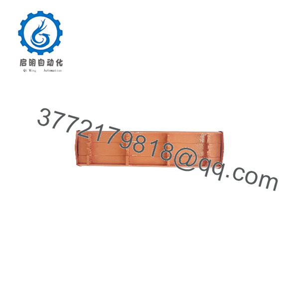
FTA-544
Installation & Configuration Guide
1.Pre-Installation (Preparation & Safety):De-energize field loops and equip ESD protection.
Isolate field loop power feeds to the targeted FTA channels following plant lock-out/tag-out (LOTO) procedures. Attach a grounded ESD wrist strap before handling the replacement FTA board. Document and photograph all existing field terminal wire numbers and shield drain wire connections.
2.Removal of Legacy Board:Disconnect system cabling and field terminals.
Unclip the multi-pin system ribbon cable connecting the FTA board to the Safety Manager I/O rack. Unscrew the field wiring terminals carefully using a precision flathead screwdriver, tagging any loose conductors. Release the DIN rail retention latches and lift the old FTA assembly off the mounting rail.
3.Installation & Wiring Execution:Mount assembly and reconnect field conductors.
Snap the new FTA-544 assembly securely onto the DIN rail. Reconnect all field signal wires and shield drain wires to their corresponding terminal screws, torqueing to specification (0.5 Nm). Firmly seat the multi-pin system ribbon cable into the board’s header connector, ensuring side locking latches click into place.
4.Power-On & Loop Testing:Verify channel continuity and signal calibration.
Restore field loop power and verify that 24V DC loop supply voltages are stable across all terminal pairs using a calibrated multimeter. Check the Safety Manager engineering station to ensure zero signal open-circuit or ground-fault alarms exist across all 16 analog input channels.
Firmware/Software Versions & Upgrade Notes
As a passive Field Termination Assembly, the contains no programmable microcode or onboard flash memory. Its operation is purely hardware-based, relying on copper traces, terminal blocks, and connector pinouts to pass analog signals to FSC or Safety Manager I/O cards.
- Hardware Compatibility: Fully compatible with Honeywell Safety Manager (R100–R310) and legacy FSC (v7.0–v11.x) safe analog input modules (such as the SAI-1620MA and FS-SAI-1620MA).
- Ribbon Cable Cable Integrity: Ensure that the connecting pre-fabricated system cable (e.g., FSC cable assembly) matches the pinout specification required by the assigned I/O slot.
- Maintenance Precaution: Swapping an FTA board requires zero software updates or firmware flashing on the Safety Manager CPU. However, always perform physical replacement while the affected channels are bypassed or during a planned outage to prevent spurious trips.
Frequently Asked Questions (FAQ)
Is this Honeywell unit brand new or refurbished?
This product is a Brand New Surplus unit. It is not pulled from an operational cabinet, not salvaged from a decommissioned plant, and not refurbished. It comes directly from unused facility overstock in original anti-static packaging, ensuring zero solder stress or physical wear.
Why shouldn’t I buy a refurbished or pulled board?
Field termination assemblies endure continuous environmental exposure inside control cabinets. Refurbished or pulled boards often suffer from degraded terminal screw threads, invisible micro-cracks in copper traces, or oxidation on multi-pin system connectors. These defects can introduce intermittent resistance into 4-20mA loops, triggering false safety shutdowns or corrupting sensor readings. Buying New Surplus guarantees clean contacts and 100% signal reliability.
Does the include onboard fuses for channel protection?
Depending on the specific board revision, field termination assemblies utilize either onboard surface-mount protective components or series resistors to safeguard system cables against field short circuits. Refer to your system manual’s terminal connection diagram to verify specific fusing requirements for your loop architecture.



