
 WhatsApp: +86 16626708626
 Email:
  Phone: +86 16626708626
Description
Key Technical Specifications
| Parameter | Value |
|---|---|
| Manufacturer | Honeywell |
| Model | FTA-T-14 |
| Product Type | Fail-safe analog input Field Termination Assembly |
| System Compatibility | Honeywell FSC / Safety Manager systems |
| Signal Type | 0(4)-20 mA analog input |
| Number of Channels | 16 channels |
| Channel Arrangement | 2 groups of 8 channels with common 0 V |
| Connected I/O Module | Honeywell 10105/2/1 fail-safe high-density analog input module |
| Field Interface | Screw terminals |
| System Interface | SIC (System Interconnection Cable) connector |
| External Supply | 30 VDC |
| Input Current Range | 0 to 25 mA |
| Input Resistance | 250 Ω ±1% |
| Fuse Rating | 315 mAT slow-acting |
| Mounting Type | TS32 / TS35 × 7.5 DIN rail |
| Dimensions | 200 × 70 × 60 mm |
| Maximum Wire Size | 2.5 mm² (AWG 14) |
| Terminal Tightening Torque | 0.5 Nm |
| Hazardous Area Capability | Class I, Division 2 applications (system dependent) |
The Honeywell FTA-T-14 is a fail-safe 0(4)-20 mA analog input Field Termination Assembly used with Honeywell FSC/Safety Manager systems. It provides the interface between field transmitters and the fail-safe high-density analog input module 10105/2/1 through a System Interconnection Cable (SIC).
The module provides 16 analog input channels, divided into two groups of eight channels with common 0 V reference. It uses DIN rail mounting and screw terminals for direct field wiring termination.
Product Introduction
The Honeywell FTA-T-14 is a Field Termination Assembly designed for Honeywell FSC and Safety Manager safety control platforms. It connects industrial transmitters, sensors, and analog field devices to fail-safe analog input modules using a dedicated SIC interface cable.
The module is commonly used in safety-related process applications requiring 0(4)-20 mA signal monitoring. Replacement work requires verification of the connected FSC hardware, SIC cable type, field wiring assignment, and safety application configuration before commissioning.
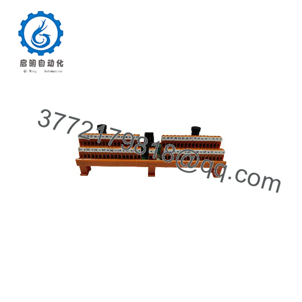
FTA-T-14
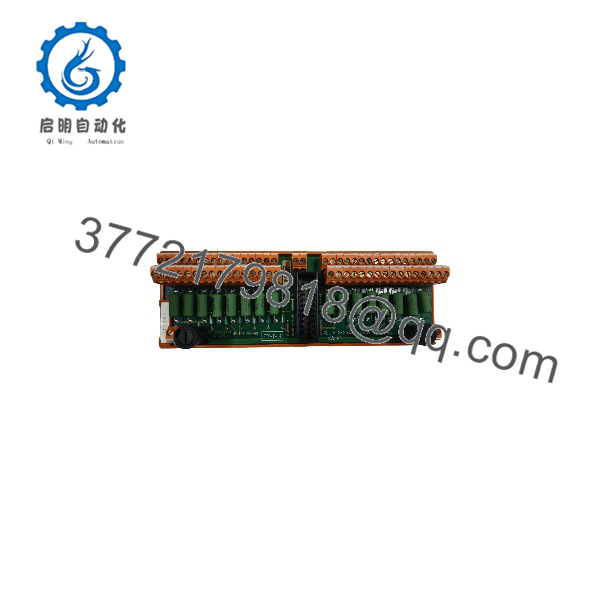
FTA-T-14
Installation & Configuration Guide
Stage 1: Pre-Installation Preparation — Approximately 20 Minutes
⚠️ Safety First:
The FTA-T-14 may be installed in safety-related measurement circuits. Before replacement, place the Safety Manager/FSC system into an approved maintenance state. Apply lockout/tagout procedures where required and isolate connected field power sources.
Tools Required:
- ESD wrist strap
- Digital multimeter
- Insulated screwdriver set
- Wire labels
- Smartphone for cabinet photographs
- Honeywell FSC/Safety Manager documentation
- Torque screwdriver
Data Backup:
- Record the complete module identification:
- FTA-T-14
- Serial number
- Hardware revision
- Photograph:
- Field terminal wiring
- SIC cable connection
- DIN rail mounting position
- Fuse locations
- Document:
- Connected transmitter loops
- Channel assignments
- 0 V/common wiring
- Associated 10105/2/1 input module
- Verify replacement compatibility.
⚠️ Important:
The FTA-T-14 is not a universal analog terminal block. Incorrect channel mapping can cause incorrect process values or safety alarms.
Stage 2: Removing the Old Module — Approximately 15 Minutes
- Place the safety system in maintenance mode.
- Verify field power is isolated.
- Label all field wires before removal.
- Disconnect:
- Field signal terminals
- External power connections
- SIC cable connector
- Release DIN rail locking mechanism.
- Remove the module.
- Inspect:
- Terminal screws
- Fuse holders
- SIC connector pins
- DIN rail condition
- Cable insulation
⚠️ Keep the original module until testing is complete.
The old FTA provides the reference for channel wiring and field termination.
Stage 3: Installing the New — Approximately 20 Minutes
- Verify the replacement part number is .
- Confirm:
- 16-channel analog input configuration
- Correct FSC/Safety Manager application
- Compatible SIC cable connection
- Mount the module on the DIN rail.
- Connect the SIC cable.
- Reconnect field wiring channel by channel.
- Verify:
- Signal polarity
- Channel numbering
- Common 0 V connections
- Tighten terminals to approximately 0.5 Nm.
Self-Checklist:
- Correct model confirmed
- SIC connector fully seated
- Field channels matched
- 0 V common wiring verified
- Fuse rating checked
- Terminal torque completed
- DIN rail locking secure
Stage 4: Power-On & Testing — Approximately 30 Minutes
- Perform a final wiring inspection before energizing.
- Restore system power according to site procedure.
- Check Safety Manager diagnostics.
- Verify analog input values.
- Test connected transmitters:
- 0 mA
- 4 mA
- 20 mA
- Confirm:
- Correct channel indication
- No open-loop alarms
- No communication faults
- Perform required safety validation checks.
⚠️ Troubleshooting Note:
- All channels fail: Check SIC cable connection and upstream I/O module.
- One channel fails: Check field wiring, transmitter loop, and terminal connection.
- Incorrect analog value: Verify channel assignment and scaling configuration.
- Fuse failure: Check external loop wiring for short circuits before replacement.
Frequently Asked Questions (FAQ)
Can the Honeywell be hot-swapped?
No. The is used in Safety Manager/FSC safety-related I/O systems. Disconnect power and follow site maintenance procedures before removing field wiring or the module.
What is the main function of ?
The terminates 0(4)-20 mA analog field signals and connects them to Honeywell fail-safe analog input modules through the SIC interface.
How many analog channels does support?
The module provides 16 analog input channels. The channels are arranged as two groups of eight with a common 0 V reference.
Is compatible with standard Honeywell analog input modules?
No. The is designed for specific Honeywell FSC/Safety Manager architectures, including connection with the 10105/2/1 fail-safe analog input module. Verify the exact I/O configuration before installation.
Does replacing require software configuration changes?
Usually the FTA itself does not contain application logic, but channel wiring and I/O configuration must match the existing Safety Manager project. Always verify channel assignments after replacement.
Why is available as surplus stock?
Legacy safety system components remain in demand because many plants continue operating installed FSC and Safety Manager systems. Spare availability usually comes from unused inventory, system upgrades, and maintenance stock.
What should I request before purchasing a Honeywell ?
Request:
- Actual module photos
- Nameplate image
- Serial number
- Condition confirmation:
- New Original / New Surplus
- Refurbished (tested)
- Functional inspection record
- Warranty details
For safety applications, verify the complete FSC/Safety Manager hardware configuration before installation.



