
 WhatsApp: +86 16626708626
 Email:
  Phone: +86 16626708626
Description
Key Technical Specifications
| Parameter | Value |
|---|---|
| Manufacturer | Honeywell |
| Model Number | TC-PPD011 |
| Product Type | Battery extension module |
| Primary Function | Supports backup battery capacity for controller memory retention during loss of normal power |
| Controller Platform | Honeywell C200 / TC-series process-controller chassis |
| Chassis Family | Chassis Input/Output Modules Series A, based on available closely related TK-PPD011 documentation |
| System Supply Reference | 24 V DC controller system |
| Maximum Voltage Rating | 30 V DC, based on market reference for TC-PPD011 |
| Current Draw at 24 V DC | 0.036 A, based on closely related PPD011 module reference |
| Current Draw at 5 V DC | 0.112 A, based on closely related PPD011 module reference |
| Approximate Dimensions | 3.5 cm H × 14 cm W × 14.5 cm D, based on closely related PPD011 module reference |
| Approximate Weight | 0.36 kg, based on closely related module reference |
| Chassis Form Factor | Confirm single-wide or double-wide occupancy from the installed chassis arrangement and complete Honeywell documentation |
| Related Part References | 51309241-125 and 51309241-175 appear in market listings; verify the exact part number and suffix on the installed unit before procurement |
| Installation Environment | Honeywell C200 controller chassis / compatible TC-series controller chassis |
| Lifecycle Status | Legacy DCS controller-support spare; confirm exact Honeywell lifecycle status, suffix revision, and authorized replacement path before a last-time-buy |
| Stocking Recommendation | Min: 1 module per critical common controller-chassis design, plus the correct approved battery; Max: 2 only if multiple independent control systems share the same configuration and supplier lead time variability exceeds the plant recovery target |
Available market references identify TC- as a Honeywell battery extension module, while documentation for the closely related TK- identifies a Honeywell battery extension module for the Chassis Input/Output Modules Series A platform with 0.036 A current draw at 24 V DC, 0.112 A at 5 V DC, 0.36 kg weight, and 3.5 cm × 14 cm × 14.5 cm dimensions. The TC and TK variants must not be treated as interchangeable without verified Honeywell documentation.
Product Introduction & Supply Chain Strategy
The Honeywell TC-PPD011 is a battery extension module used in compatible Honeywell C200 or TC-series controller chassis. It supports battery-backed retention functions so controller memory and system-state information remain protected during an interruption of normal control power. It is a controller-support module, not an analog-input or general I/O module; claims that identify it as a 16-channel analog input are inconsistent with multiple battery-extension references.
This product is a Brand New Surplus unit. It is not used, not pulled from a decommissioned plant, and not refurbished. All modules undergo rigorous quality verification to ensure OEM-level reliability. The module has a modest purchase value, but failure during a controller-power event can create high recovery cost if configurations or retained data are unavailable. Maintain one verified buffer stock unit, monitor battery age, and use vendor consolidation for common C200 chassis spares to reduce total carrying cost.
Installation & Configuration Guide
Stage 1: Pre-Installation
- Obtain approved DCS maintenance authorization and coordinate the work with operations, the control-room operator, cybersecurity personnel, and the Honeywell system owner.
- Identify the controller chassis, C200 or TC controller type, battery extension module location, associated battery part number, controller redundancy arrangement, and all process units controlled by the chassis.
- Record the controller serial number, chassis serial number, TC- label, related Honeywell part number, hardware revision, battery date code, installed software release, controller database revision, and active diagnostic status.
- Back up the complete controller configuration before touching hardware. Preserve the Experion PKS project, controller database, control strategies, I/O configuration, peer-control communications, network settings, alarm configuration, firmware baseline, and recovery procedure.
- Record active alarms, controller diagnostics, power-supply status, redundancy state, battery-health status, event history, forced points, bypasses, inhibited alarms, and any maintenance overrides.
- Confirm whether the controller architecture supports online replacement of the battery extension module. Do not assume that this module is hot-swappable because the controller remains powered.
- Evaluate retained-memory risk. If battery replacement or module removal can affect retained configuration, sequence state, or time-dependent functions, place the process in an approved safe condition first.
- Apply lock-out/tag-out to the relevant 24 V DC controller supply and chassis circuits if the approved Honeywell maintenance procedure requires power isolation.
- Verify that the control supply is stable and that the module is within its approved voltage range. A market reference lists TC- at 30 V DC maximum, while a closely related reference lists 24 V DC and 5 V DC current requirements.
- Wear a grounded ESD wrist strap and use ESD-safe handling controls before contacting module connectors, chassis interfaces, or battery-related components.
- Photograph the chassis, module location, associated controller, battery connections, cable routing, connector orientation, grounding hardware, and module labels.
- Confirm the replacement is the exact TC- configuration required by the installed chassis. Verify the full Honeywell part number and suffix; do not substitute TK-, 51309241-125, or 51309241-175 solely on name similarity.
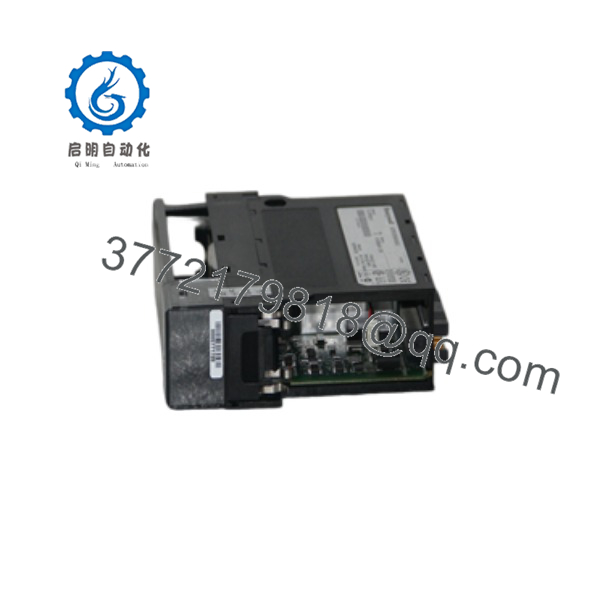
TC-PPD011
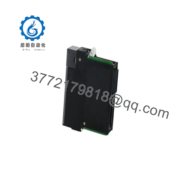
TC-PPD011
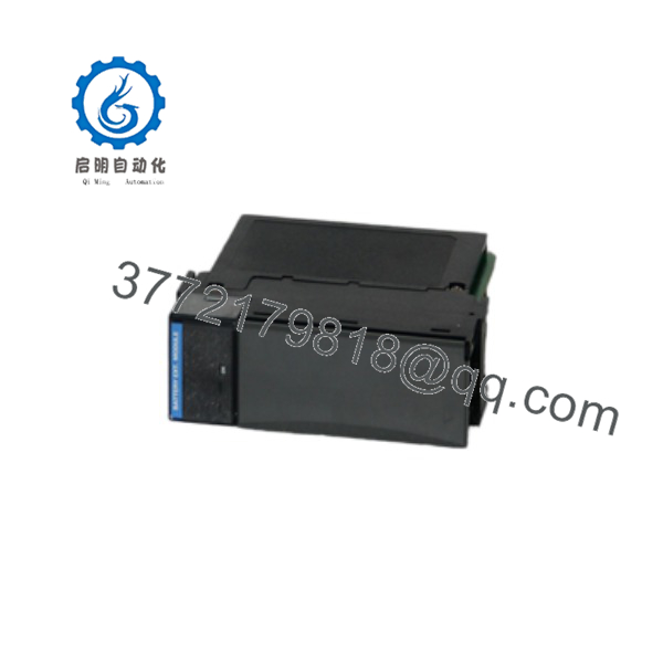
TC-PPD011
Stage 2: Removal
- Confirm controller status, redundancy status, backup completion, and operations approval before removing the module.
- If the procedure calls for controller shutdown, place the process under approved backup control or safe-state operation before isolating the chassis.
- If the procedure permits removal while the controller is powered, follow the exact Honeywell-approved method. Do not improvise on a battery-backed controller component.
- Disconnect any battery connection or module interface only after documenting its polarity, connector orientation, retention latch, and cable path.
- Release the module using the specified latch, clip, screw, or chassis retention mechanism.
- Withdraw the TC- evenly from the chassis or mounting position. Avoid twisting the module, forcing connectors, or touching exposed contacts.
- Inspect the chassis connector, battery interface, card guide, mounting hardware, grounding points, and adjacent controller modules for bent contacts, corrosion, contamination, heat damage, loose hardware, or unstable power indicators.
- Inspect the associated battery for leakage, swelling, corrosion, damaged insulation, expired service date, or incorrect part number. Follow site environmental and hazardous-waste procedures for battery handling and disposal.
- Place the removed module in ESD-safe packaging. Label it with the asset number, controller/chassis location, installed battery information, observed fault symptoms, removal date, and configuration-backup reference.
Stage 3: Installation
- Compare the New Surplus TC- label with the removed module and approved cabinet records. Confirm the exact model, related Honeywell part number, hardware revision, connector layout, mounting arrangement, and chassis compatibility.
- Inspect the replacement module for shipping damage, corrosion, damaged contacts, missing labels, or evidence of improper storage.
- Confirm that the approved battery type, voltage, chemistry, connector, and date code meet the Honeywell system maintenance specification. Do not install an unverified replacement battery.
- Align the module with its designated chassis or mounting location and insert it evenly. The module should seat without excessive force.
- Engage all latches, screws, clips, or retention hardware fully.
- Restore battery connections with exact polarity and connector orientation. Do not force connectors or alter wiring to make a different battery fit.
- Restore protective earth, shielding, cable restraints, and enclosure covers exactly as documented.
- Confirm that the controller power supply, chassis fans, grounding, and adjacent modules are in normal condition before restoring power.
- Do not modify controller firmware, application software, I/O wiring, network configuration, or unrelated chassis modules during a direct TC- replacement unless separately approved.
Stage 4: Power-On & Testing
- Measure the 24 V DC controller power supply before energization and verify stable voltage, polarity, grounding, and current capacity.
- Restore chassis power according to the approved Honeywell startup sequence.
- Observe controller status, chassis indicators, power diagnostics, battery status, redundancy status, and communication diagnostics during initialization.
- Confirm that the controller starts normally and that the existing control database, retained configuration, application revision, and communications settings are present and correct.
- Verify the controller’s current time, event sequence, historical data behavior, restart state, and any application-specific retained variables according to the site recovery procedure.
- Confirm healthy communications with operator stations, supervisory servers, peer controllers, remote I/O, network interfaces, and redundancy partners.
- Review controller diagnostics for battery, memory, power, configuration, or chassis faults.
- Perform the approved functional test. Verify that critical loops, alarms, interlocks, and shutdown logic remain correct without changing process setpoints unless operations approves the test.
- Remove temporary bypasses, forced values, or maintenance overrides only under approved control.
- Record the replacement module identification, battery part number and date code, controller software baseline, installation time, technician, test results, and remaining buffer-stock quantity.
Firmware/Software Versions & Upgrade Notes
- Recommended firmware version: Retain the installed and validated Honeywell controller firmware, Experion PKS release, controller database revision, and application configuration during a direct TC- replacement. The battery extension module itself does not normally require user-managed firmware.
- Configuration retention: The reason to control this module carefully is memory-retention continuity. Before replacement, preserve the controller application, configuration database, control strategies, communications settings, time settings, and recovery media in a verified backup location.
- Part-number control: TC- references appear alongside related part numbers 51309241-125 and 51309241-175 in market listings. Closely related TK- information should be used only as a preliminary reference, not as proof of direct compatibility. Confirm the full installed label and Honeywell documentation before purchasing or installing.
- Battery compatibility: Use only the controller-approved battery type. Battery voltage, connector style, chemistry, charging characteristics, and physical dimensions can affect retention capability and module safety.
- Backward compatibility: An earlier controller release may have different battery diagnostics, alarm handling, or chassis module recognition. Confirm the replacement module revision against the installed Honeywell software baseline.
- Forward compatibility: A later module revision may require a different controller release, chassis revision, battery assembly, or approved service procedure. Treat any revision difference as a controlled engineering change.
- Upgrade warning: Do not upgrade Honeywell controller firmware, Experion PKS software, or database configuration during an emergency battery extension module swap. Firmware changes can add application conversion, network compatibility, cybersecurity, validation, and process-risk work.
- Downgrade warning: Do not restore an older controller database or firmware release unless compatibility with the installed chassis, processor, I/O modules, and application version is confirmed. An uncontrolled downgrade can alter control behavior or remove validated configuration changes.
- Spare-control recommendation: Store the New Surplus TC- with the approved battery part number, battery replacement interval, controller chassis compatibility record, current configuration backup, software baseline, recovery procedure, and commissioning checklist.
Frequently Asked Questions (FAQ)
Are these really new units?
Yes. This inventory standard applies only to New Original / New Surplus modules. A New Surplus TC- should show no chassis insertion marks, damaged contacts, altered labels, corrosion, contamination, battery leakage residue, heat discoloration, or evidence of board-level modification. Incoming QC should verify the model marking, part number, hardware revision, connector condition, enclosure integrity, ESD-safe packaging, and traceability documentation where available.
Why is New Surplus pricing lower than OEM new but higher than lower-cost alternatives?
OEM-new pricing reflects active manufacturer channels, support arrangements, and standard commercial terms. New Surplus pricing reflects the cost of locating, verifying, preserving, and warranting genuine legacy Honeywell controller hardware. Lower-cost alternatives can carry poor storage history, damaged connectors, corrosion from battery exposure, altered electronics, wrong part-number variants, or unknown compatibility. The relevant calculation is Total Cost of Ownership (TCO): the cost of the module plus the risk of controller recovery, process disruption, configuration restoration, and lost production.
Is the TC- obsolete or EOL?
Treat the TC- as a legacy Honeywell controller-support spare until Honeywell or an authorized channel confirms its exact lifecycle and replacement status. Public market sources show ongoing availability, but they do not prove active manufacturing, official support status, or interchangeability among TC and TK variants.
For a production-critical controller chassis, keep one verified buffer stock module and at least one approved battery on-site. Review the last-time-buy need based on installed population, expected controller life, battery replacement schedule, supplier lead time variability, and availability of an engineering-approved migration path.
Can I hot-swap the TC-?
Do not assume hot-swap capability. The battery extension module supports memory-retention functions, so removal may affect controller behavior, diagnostics, or retained data depending on chassis design and controller state. Follow the exact Honeywell procedure for the installed C200 or TC-series chassis. If no approved online-replacement procedure exists, place the controller and process in a safe, planned maintenance state.
Will replacing the module erase the controller program?
It should not erase a properly retained controller program when the system is healthy and the correct procedure is followed, but you must not rely on that assumption. Back up the complete controller configuration before replacement. After installation, verify the application revision, controller database, configuration checksum, time, communications, and critical control-loop behavior before returning the system to normal service.
Can I substitute TK- or another Honeywell battery module?
Not without an engineering-approved compatibility check. Market information describes TK- as a battery extension module with related part number 51309241-175, while TC- references include other suffixes such as 51309241-125. These references may reflect different revisions, chassis platforms, regions, or documentation conventions. Match the exact full part number, connector arrangement, battery specification, chassis location, controller version, and Honeywell-approved documentation before substitution.
What warranty and quality documentation should accompany this spare?
Specify a written 12 month warranty, subject to ESD-safe storage, correct battery handling, approved installation, and compatible controller operation. Require module label and serial-number photographs, part-number and revision verification, connector inspection, packaging evidence, power-on or functional-test records where an approved test setup is available, and final QC sign-off. Store those records with the controller asset file, configuration backup, battery maintenance record, and commissioning checklist so the controller can be restored quickly after an unplanned event.



