WhatsApp: +86 16626708626
 Email:
 Phone: +86 16626708626
Description
Core Product Summary (Brand / Model / Key Attributes)
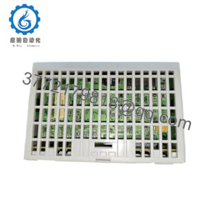
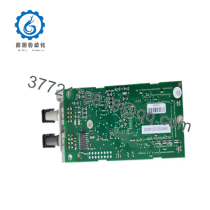
The Honeywell VFD_6713_V2 is an internal electronic circuit board sub-assembly engineered for Honeywell SmartVFD series variable frequency drives. Used across HVAC and industrial motor control applications, this board provides sub-level power management, gate driving, and control processing for Honeywell drive power sections.
Designated by the board-level silk screen marking VFD_6713_V2, the component functions as an internal spare part or replacement control card within larger SmartVFD drive assemblies (such as the HVFD series). The board routes internal DC bus voltages, processes gate signals for power switches, and interfaces with the drive’s main control interface and diagnostic LED/keypad buses.
Key Technical Specifications
| Parameter | Specification |
|---|---|
| Manufacturer | Honeywell |
| Model / Board Marking | VFD_6713_V2 |
| Component Type | Internal Drive Printed Circuit Board (PCB) Assembly |
| System Integration | Honeywell SmartVFD / HVFD Drive Series |
| Function | Internal Gate Drive & Power Control Processing |
| Operating Temperature Range | -10°C to +50°C (standard industrial drive enclosure rating) |
Detailed Product Overview
The Honeywell VFD_6713_V2 serves as an internal hardware sub-assembly for Honeywell SmartVFD variable frequency drives. In industrial HVAC fan and pump applications, it handles internal signal conditioning and firing sequence commands generated by the drive’s main processor.
Because VFD_6713_V2 is an internal board-level designation (typically stamped directly on the PCB), it is primarily referenced during component-level repair, field servicing, or internal module replacement within a Honeywell drive housing. The board contains surface-mount components, signal headers, and power trace buses designed to integrate directly with the drive chassis.
Installation requires handling electronic circuit assemblies under strict ESD (electrostatic discharge) safety standards, ensuring all DC bus capacitors are fully discharged prior to servicing or replacement.
Engineering Selection Highlights
- Board-Level Identification: Exact PCB part marking VFD_6713_V2 confirms physical layout and electrical trace compatibility for specific Honeywell SmartVFD drive chassis.
- SmartVFD System Compatibility: Designed to function within Honeywell’s HVAC commercial variable frequency drive platform.
- Internal Drive Repair Component: Facilitates targeted board-level servicing of Honeywell drive units without requiring complete chassis replacement when outer housing remains intact.
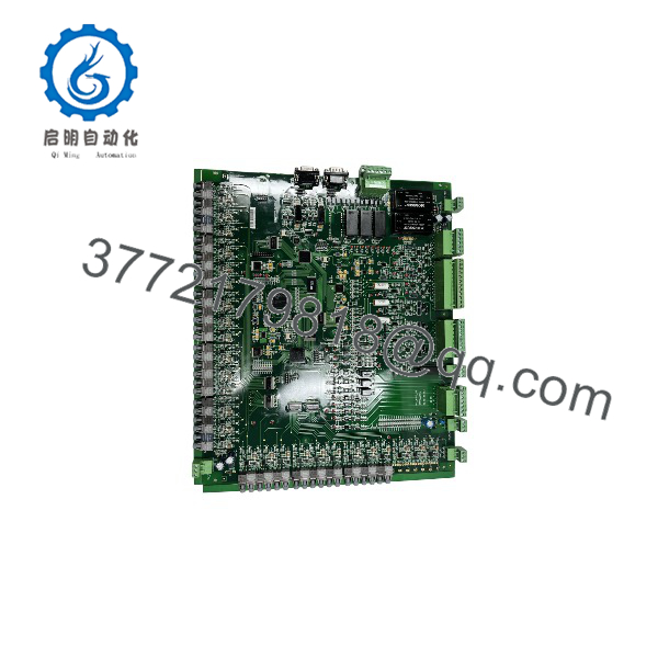
VFD_6713_V2
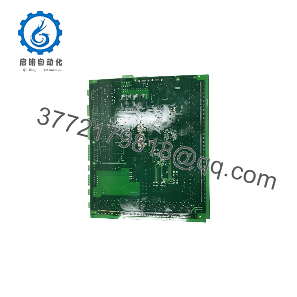
VFD_6713_V2
System Compatibility & Integration Requirements
| Item / Dependency | Verified Compatibility or Requirement | Practical Note |
|---|---|---|
| System Family | Honeywell SmartVFD / HVFD Series | Serves as internal sub-assembly hardware |
| Installation Requirements | ESD-Safe Field Service Environment | Must be installed inside compatible Honeywell drive chassis |
| Power Handling | DC Bus & Gate Drive Voltages | Requires full de-energization and capacitor discharge before installation |
Dimensions, Mounting & Connection Notes
- Mounting Method: Mounts internally to the drive chassis backplate via standard PCB standoff screws and alignment pins.
- Interconnections: Connects to the main control card and power stage using internal ribbon cables, multi-pin headers, and direct busbar contacts.
- ESD Caution: Standard ESD precautions (grounded wrist strap) must be observed during handling to prevent damage to sensitive CMOS logic components.
- Safety Clearance: Verify that all high-voltage clearances and insulation barriers match the original drive chassis layout during installation.
FAQ
What is the Honeywell VFD_6713_V2?
The Honeywell VFD_6713_V2 is an internal printed circuit board (PCB) assembly used inside Honeywell SmartVFD variable frequency drives.
Is VFD_6713_V2 a complete standalone drive?
No, VFD_6713_V2 is an internal circuit board sub-assembly, not a complete standalone VFD in an enclosure.
Where can I find the model number VFD_6713_V2?
This designation is typically silkscreened directly onto the fiberglass circuit board inside the drive assembly.
How is the VFD_6713_V2 installed?
It is installed inside the drive housing using internal chassis screws, ribbon cable connectors, and pin headers during drive servicing.
Verification & Troubleshooting Notes
- Capacitor Discharge Verification: Before attempting to inspect or replace the VFD_6713_V2 board, disconnect incoming AC line power from the drive unit and measure the DC bus terminals with a calibrated voltmeter to confirm voltage has dropped below 50V DC.
- Visual Inspection: Inspect the board surface for visible burn marks, compromised trace lines, or bulged electrolytic capacitors before re-energizing.
- Ribbon Cable Alignment: Ensure all multi-pin ribbon cables and header jumpers are fully seated and locked in their respective connectors during reassembly.
- Grounding Connection: Confirm that chassis ground screws securing the PCB are properly torqued to maintain ground reference and noise immunity.