
 WhatsApp: +86 16626708626
 Email:
  Phone: +86 16626708626
Description
Key Technical Specifications
| Parameter | Value |
|---|---|
| Manufacturer | ICS Triplex / Rockwell Automation |
| Model | 9402 / T9402 |
| Product Family | AADvance 9000 Series |
| Module Type | Digital Input |
| Number of Channels | 16 |
| Nominal Field Voltage | 24 VDC |
| Input Measurement Range | 0–32 VDC |
| Input Measurement Resolution | 5 mV |
| Input Measurement Accuracy | ±0.5 V |
| Channel Isolation | 1.5 kVDC for 1 minute |
| Channel Configuration | Isolated |
| Module Dimensions | 166 × 42 × 118 mm |
| Weight | Approximately 340 g |
| Termination Assembly | T9801/T9802/T9803 family, depending on architecture |
| System | AADvance safety controller |
| Maximum Safety Integrity | SIL 3 for a single channel, subject to system configuration |
The AADvance reference documentation specifies that the T9402 monitors 16 isolated digital input channels, measures input voltage from 0 to 32 VDC, provides 5 mV resolution, and has a 1.5 kVDC isolation withstand rating for 1 minute.
The module measures field input voltage rather than simply presenting a binary state to the controller. This allows the controller to receive both digital-state information and voltage data from each channel.
Product Introduction
The ICS Triplex 9402 / T9402 is a 16-channel, 24 VDC isolated digital input module for the AADvance safety controller. It monitors discrete field signals and provides channel state and voltage information to the controller. Typical applications include emergency shutdown, burner management, fire and gas systems, and other safety-related process functions.
The important distinction is channel isolation. Each input is isolated, which matters when field devices operate at different electrical potentials or when fault containment is part of the safety design. The 9402 is also physically different from the 9401: 9401 provides 8 inputs, while 9402 provides 16.
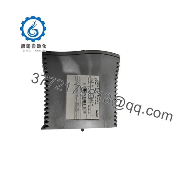
9402
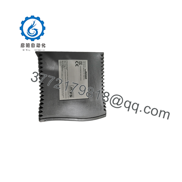
9402
Installation & Configuration Guide
Stage 1: Pre-Installation Preparation — Approximately 10 Minutes
⚠️ Safety First: The 9402 can form part of a safety instrumented system. Notify operations, place the process in the approved safe state, follow the site’s lockout/tagout procedure, and implement the required SIS bypass or override procedure before removing the module.
Tools Required:
- ESD wrist strap
- PH1/appropriate screwdriver
- Calibrated multimeter
- Wire labels
- Smartphone for photographs
- Approved AADvance engineering workstation
- Current AADvance application/configuration backup
Data Backup:
- Record the complete module marking: 9402 / T9402.
- Record the chassis and I/O base location.
- Photograph the installed module.
- Photograph the termination assembly.
- Record all 16 channel assignments.
- Identify every connected field device.
- Save the current AADvance application.
- Record the controller configuration and module status.
- Record any diagnostic conditions before removal.
- Verify the termination assembly type.
⚠️ Do not treat the 9402 as a generic 24 VDC PLC input card. It belongs to the AADvance safety-controller architecture and must be configured and tested within that system.
Stage 2: Removing the Old Module — Approximately 5 Minutes
- Confirm the process is in the approved maintenance state.
- Verify the relevant safety functions are properly bypassed or otherwise managed.
- Follow the AADvance maintenance procedure.
- Identify the exact I/O base and module position.
- Photograph the module and adjacent modules.
- Confirm field wiring identification at the termination assembly.
- Release the module’s retention mechanism.
- Remove the module carefully from the base.
- Inspect the mating connector.
- Check for contamination, damaged contacts, or mechanical damage.
⚠️ Do not pull against the termination wiring. The field wiring terminates separately from the plug-in module, so mechanical force should remain on the module itself.
Keep the original 9402 available until the replacement passes system diagnostics and the required functional test.
Stage 3: Installing the New Module — Approximately 5–10 Minutes
- Verify the replacement model is 9402/T9402.
- Confirm that it is the 16-channel digital-input version.
- Verify the module belongs in the intended AADvance I/O base position.
- Put on the grounded ESD strap.
- Inspect the base connector.
- Align the module correctly.
- Insert the module without forcing it.
- Engage the mechanical retention mechanism.
- Verify that the associated termination assembly and cable are secure.
- Confirm the field wiring remains correctly identified.
Configuration Clone — Critical
The 9402 has 16 isolated input channels. Before returning it to service, verify every channel against the approved I/O schedule.
Check:
- Channel number
- Field device
- Input function
- Normal state
- Alarm state
- Trip state
- Channel diagnostics
- Application tag
- AADvance configuration
- Termination assembly
- Input voltage
The AADvance architecture uses T9801/T9802/T9803 termination assemblies for the digital-input modules, corresponding to simplex, duplex, and triplex configurations.
Self-Checklist:
- 9402/T9402 verified
- Correct I/O base position
- 16-channel configuration verified
- Termination assembly verified
- Field wiring identified
- ESD precautions followed
- Module seated correctly
- Application configuration backed up
- Channel assignments verified
- Diagnostics checked
Stage 4: Power-On & Testing — Approximately 10–20 Minutes
- Complete a visual inspection before restoring power.
- Verify the termination assembly and module are correctly seated.
- Restore system power according to the approved AADvance procedure.
- Observe module status indications.
- Check the AADvance engineering workstation for module diagnostics.
- Confirm the 9402 is recognized in the correct I/O position.
- Verify all 16 channels.
- Check the measured voltage for representative input channels.
- Verify the digital state of each required input.
- Perform a controlled field simulation or proof test according to the site’s safety procedure.
- Verify alarm and trip logic.
- Confirm no unexpected diagnostic faults remain.
- Remove maintenance bypasses only after the approved functional test passes.
⚠️ Do not simply jumper 24 V onto every channel to prove the module works. For a safety application, the correct test must verify the complete signal path, including field device behavior, termination assembly, input channel, application logic, alarm handling, and final safety action.
Technical Pitfalls and Survival Guide
1. 9401 vs. 9402
❗ This is an easy procurement mistake.
- 9401: 8-channel digital input
- 9402: 16-channel digital input
Both belong to the same AADvance family, but the channel count is different. The system configuration must match the installed hardware.
2. vs. 9402 Naming
You may encounter listings using , 9402, or 9402-0001. A supplier listing identifies as a 16-channel digital input module and gives 9402-0001 as a part number.
Do not purchase solely on the short “9402” designation. Request a photograph of the actual nameplate and confirm the complete ordering code.
3. Input Voltage
The module measures 0–32 VDC. Do not assume that every 24 VDC field signal is acceptable simply because the nominal system voltage is 24 VDC. Verify the actual field-device voltage and signal characteristics.
4. Termination Assembly Compatibility
The termination assembly is part of the physical I/O architecture. Verify whether the installed system uses the simplex, duplex, or triplex termination arrangement before ordering associated hardware.
5. Safety Certification Does Not Equal Automatic SIL 3
The documentation identifies SIL 3 as the maximum achievable SIL for a single channel, but the actual achieved SIL depends on the selected CPU, input/output voting architecture, diagnostics, application, and system configuration.
Do not write “SIL 3 certified” on a purchase specification as though the individual module alone determines the safety integrity of the entire function.
Frequently Asked Questions (FAQ)
What is the ICS Triplex 9402?
The ICS Triplex 9402, also identified as , is a 16-channel isolated digital input module for the AADvance safety controller. It accepts 24 VDC-class field signals and measures input voltage over a 0–32 VDC range.
What is the difference between 9401 and 9402?
The difference is primarily channel count:
- 9401: 8 isolated digital inputs
- 9402: 16 isolated digital inputs
The AADvance documentation explicitly lists these two modules with 8 and 16 channels respectively.
If the existing application uses a 9402, do not substitute a 9401 merely because the available input channels appear sufficient. Verify the system configuration and termination arrangement first.
Is the 9402 a 24 VDC input module?
Yes. The module is specified as a 24 VDC digital input module, with an input measurement range of 0–32 VDC.
The actual field voltage should still be measured during commissioning rather than assumed from the nominal system voltage.
Is the 9402 isolated?
Yes. The 9402 provides isolated digital input channels, with the documentation specifying a maximum channel-isolation withstand of 1.5 kVDC for one minute.
This is particularly relevant in safety and critical-control applications where field-side electrical faults need to be considered during system design.
Can I hot-swap the 9402?
Do not assume hot replacement is permitted simply because the module is plug-in. The correct procedure depends on the AADvance system architecture, controller state, application requirements, and site maintenance procedure.
For a live safety system, follow the applicable AADvance maintenance documentation and approved plant procedure rather than using a generic PLC hot-swap procedure.
What termination assembly does the 9402 use?
The AADvance digital-input architecture uses the T9801, T9802, or T9803 termination assemblies for simplex, duplex, and triplex configurations. The correct assembly depends on the system architecture.
Verify the existing termination assembly before ordering a complete replacement package.
Is the 9402 suitable for SIL 3 applications?
The AADvance documentation states that SIL 3 is the maximum achievable SIL for a single channel, but it also explicitly notes that the achieved SIL can increase or decrease depending on CPU selection and input/output voting configuration.
Therefore, the correct engineering statement is that the module is part of an AADvance platform designed for safety applications; the complete safety function must be assessed as a system.
What condition should I specify when buying a replacement 9402?
Specify the condition explicitly:
- New Original / New Surplus
- Factory Sealed
- Refurbished / Tested
For a safety-system spare, request photographs of the actual module label, ordering code, connectors, and physical condition. If the supplier claims functional testing, request the test report for the actual unit.
What should I provide when requesting a replacement?
Provide:
- Model: 9402 /
- Complete ordering code, if available
- AADvance controller configuration
- I/O base position
- Termination assembly
- System architecture: simplex, duplex, or triplex
- Existing application/software version
- Required condition
- Quantity required
The most important check is not simply whether the seller has a 9402. Verify the complete part number, channel count, AADvance configuration, termination assembly, and safety application requirements before installation.



