WhatsApp: +86 16626708626
 Email:
 Phone: +86 16626708626
Description
Core Product Summary
The ICS Triplex T9300 is the 3-way I/O base unit of the ICS Triplex AADvance controller. Each T9300 accepts up to three I/O modules of any type, together with their associated termination assemblies, and mounts on a DIN rail to the right of the T9100 processor base unit.
The unit contains a passive backplane that provides the electrical connections between the installed I/O modules and the T9100 processor base unit, carrying the command and response buses and the system power. T9300 base units connect to the controller through a direct plug connection on the right side of the T9100 (I/O Bus 1) and can be chained to further I/O base units; the left-side I/O Bus 2 connection is made with T9310 expansion cable assemblies. Module positions in the I/O base units are numbered from 01 to 24, so every module position in the controller is uniquely identified by its bus and slot combination. The electrical characteristics of the I/O bus interface limit the maximum length of each I/O bus to 8 m.
Key Technical Specifications
| Parameter | Value |
|---|---|
| Product type | I/O base unit (3-way) for the AADvance controller |
| Module capacity | Up to 3 I/O modules of any type, with associated termination assemblies |
| Backplane type | Passive backplane |
| Backplane function | Carries command and response buses and system power between I/O modules and the T9100 processor base unit |
| Bus architecture | I/O Bus 1 (right-side direct plug connection) and I/O Bus 2 (left-side connection via T9310 expansion cable) |
| Slot numbering | Module positions numbered 01 to 24; leftmost position is slot 01 |
| Maximum I/O bus length | 8 m (26.24 ft) per I/O bus (combination of I/O base units and expansion cables) |
| Mounting | DIN-rail mounting, positioned to the right of the T9100 processor base unit |
| Weight | 133 g (5 oz) |
Detailed Product Overview
In the AADvance architecture, the T9300 defines the physical and electrical structure of the I/O section. The processor modules mount on the T9100 processor base unit, while every I/O module mounts on a T9300 together with its termination assembly. The base unit is therefore the first component to specify when expanding an AADvance controller’s I/O count.
Each T9300 supports up to three I/O modules of any type. This means digital input, digital output, analogue input, and analogue output modules can be mixed within a single base unit as the application requires, subject to the chosen simplex, dual, or TMR configuration. The associated termination assemblies handle the field wiring and mount in conjunction with the I/O modules on the base unit.
The backplane inside the T9300 is passive. It contains no active processing elements of its own; it distributes the command and response buses and the system power that originate at the T9100 processor base unit to each module position. For an integrator, this has a practical consequence: the backplane cannot regenerate or buffer the bus signal, so the total bus length is constrained by the electrical characteristics of the I/O bus interface. Each of the two I/O buses — the combination of I/O base units and expansion cables — is limited to a maximum of 8 m.
Bus topology is split across two paths. The right side of the T9100 provides I/O Bus 1 through a direct plug connection to the first T9300, and I/O base units also chain to one another on the right side. The left-side path, I/O Bus 2, uses the T9310 expansion cable assembly, which connects a T9300 to another I/O base unit or back to the left side of the processor base unit, allowing additional rows of I/O base units to be installed. The two-bus structure divides the I/O addressing space so that every module position is uniquely identified by its bus and slot number, such as 1-01 for the leftmost slot on Bus 1.
Installation follows a fixed spatial order. The T9100 processor base unit is mounted on the DIN rails toward the left, and the T9300 I/O base units are mounted on the DIN rails to its right. This arrangement is not a wiring convenience: the direct plug connection between base units only mates when the units are mounted side by side in this order.
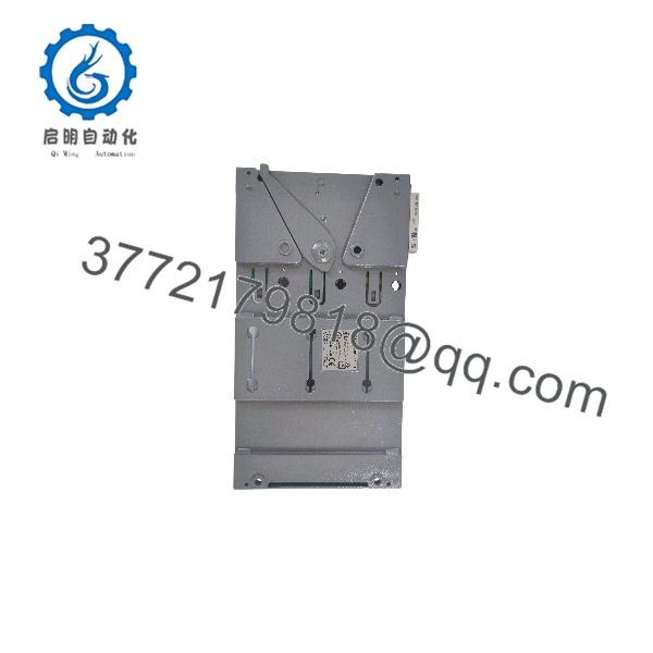
T9300
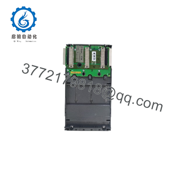
T9300
System Compatibility & Integration Requirements
| Item / Dependency | Verified Compatibility or Requirement | Practical Note |
|---|---|---|
| Controller system | ICS Triplex AADvance controller | I/O base unit of the same controller family as the T9100 processor base unit |
| I/O modules | Up to 3 I/O modules of any type per base unit | Digital and analogue I/O modules mount with their associated termination assemblies |
| Processor base unit | Connects electrically to the T9100 processor base unit | Passive backplane carries command/response buses and system power from the T9100 |
| Bus 1 connection | Direct plug connection, right side of the T9100 | First I/O base unit mates directly with the processor base unit |
| Bus 2 connection | T9310 expansion cable assembly | Connects a T9300 to another I/O base unit or to the left side of the T9100 |
| Bus length limit | 8 m (26.24 ft) maximum per I/O bus | Applies to the combination of I/O base units and expansion cables |
| Mounting position | DIN rail, to the right of the T9100 | T9100 is positioned to the left, leaving space for the I/O base units |
| Expansion ferrites | Snap-on ferrites fitted on the expansion cable | Positioned 50 mm (2 in.) from each cable end and secured with cable ties |
Dimensions, Mounting & Connection Notes
The T9300 mounts on DIN rails, positioned to the right of the T9100 processor base unit. Base units are fastened by upper and lower brackets that engage in slots on each base unit.
I/O modules install onto dowel pins on the T9300 I/O base unit. The slot in the head of the module clamp screw must be vertical before the module is pushed home, until the module connectors are fully mated with both the I/O base unit and the termination assembly connectors.
Exposed 48-pin DIN connectors on the T9300 should be covered with the black plastic protection covers supplied with the base unit for EMC static protection when positions are unoccupied.
FAQ
What is the ICS Triplex T9300?
The T9300 is the 3-way I/O base unit of the ICS Triplex AADvance controller; it carries up to three I/O modules and their termination assemblies and connects them to the T9100 processor base unit.
How many I/O modules fit on one T9300?
Each T9300 supports up to three I/O modules of any type, together with their associated termination assemblies.
Does the T9300 contain active electronics?
No. Its backplane is passive and only distributes the command and response buses and system power between the I/O modules and the T9100 processor base unit.
How is the T9300 connected to the controller?
Through I/O Bus 1, a direct plug connection on the right side of the T9100 processor base unit, and through I/O Bus 2, which uses a T9310 expansion cable assembly on the left side.
How far can the I/O bus extend?
Each I/O bus — the combination of I/O base units and expansion cables — is limited to a maximum length of 8 m by the electrical characteristics of the I/O bus interface.
How are module positions identified?
Slot positions in the I/O base units are numbered 01 to 24, with the leftmost position as slot 01; each position is uniquely identified by its bus and slot combination, for example 1-01.
Where is the T9300 mounted?
It mounts on DIN rails to the right of the T9100 processor base unit, which itself is positioned toward the left of the installation.
Are unused connector positions protected?
Yes. Exposed 48-pin DIN connectors on the T9300 should be covered with the black plastic protection covers supplied with the base unit for EMC static protection.