WhatsApp: +86 16626708626
 Email:
 Phone: +86 16626708626
Description
Key Technical Specifications
- Manufacturer: Japan Radio Co., Ltd. / JRCS
- Part Number: JSTD-M15A
- Product Type: Signal-processing printed circuit board
- Application: Marine automation and shipboard control systems
- System Family: JRCS equipment; exact host system not independently confirmed
- Primary Function: Signal processing within a JRCS automation assembly
- Input Channels: Not independently verified
- Output Channels: Not independently verified
- Signal Types: Not independently verified
- Rated Supply Voltage: Not independently verified
- Backplane or Rack Interface: Verify from the host assembly and board edge connector
- Field Wiring Interface: May require a separate JRCS terminal or interface board; verify the system wiring
- Isolation: Not independently verified
- Status Indicators: Confirm LED layout from the actual board
- Operating Temperature: Not independently verified
- Marine Approvals: Verify class approval and vessel-specific certification requirements
- Dimensions: Not independently verified
- Firmware or Configuration: System-dependent; verify host-controller compatibility
- Lifecycle: Treat as legacy or obsolete until confirmed by JRCS documentation
- Replacement Requirement: Exact part-number and revision match recommended
Publicly available information identifies JSTD-M15A as a JRCS signal-processing board, but does not provide an authoritative datasheet with channel count, signal levels, supply voltage, dimensions, or environmental ratings. Do not invent those values from similar JRCS cards.
Product Introduction
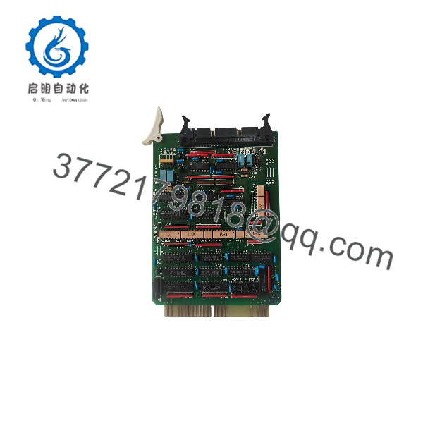
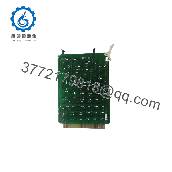
The JRCS JSTD-M15A is a Japan Radio Co. signal-processing PCB used in marine automation equipment. Available supplier records associate it with shipboard control systems, but the exact host system, electrical interface, signal capacity, and environmental specification require confirmation from the board label and vessel documentation.
This card should be sourced as an exact replacement for an installed JSTD-M15A, including revision and connector configuration. Before installation, verify the rack or controller model, mating terminal board, software configuration, marine certification requirements, and vessel wiring drawings.
JSTD-M15A
JSTD-M15A
Troubleshooting Quick Reference
| Symptom | Possible Cause | Relevance to This Part | Quick Check Method | Recommendation |
|---|---|---|---|---|
| Entire automation section is inactive | Rack power, controller fault, backplane issue, or common supply failure | ⚠️ Low to medium | Measure the host-rack supply and confirm whether adjacent cards are active | Check the rack and controller before replacing the PCB |
| Several signal channels fail together | Shared field supply, terminal interface, backplane path, or board power fault | ⚠️ Medium | Measure supply and common voltage at the associated terminal/interface board | Trace the shared circuit before condemning JSTD-M15A |
| One signal channel fails | Field sensor, wiring, terminal point, or individual processing channel fault | ✅ Medium | Compare the field signal at the terminal board with the corresponding software value | Test field wiring first, then compare the channel with a known-good input |
| Board LEDs are dark | Missing board supply, poor seating, failed regulator, or defective board | ✅ High | Measure the board supply at the rack interface and inspect connector seating with power isolated | Verify supply and connector condition before replacement |
| Controller reports a card or slot fault | Wrong board type, incorrect slot, backplane fault, or board failure | ✅ High | Record the controller diagnostic and compare the installed part number with the system configuration | Confirm exact JSTD-M15A identity and slot position |
| Signal values are intermittent | Oxidized connector, vibration, moisture, loose terminal, or failing board | ✅ Medium | Inspect edge contacts and terminals; monitor the signal while checking cable movement | Correct connection and moisture problems before replacing the card |
| Values are consistently out of range | Incorrect scaling, sensor fault, wrong signal type, or processing-board fault | ⚠️ Medium | Compare raw terminal voltage/current with software scaling and alarm limits | Verify configuration and sensor type before replacement |
| New card causes immediate system alarm | Revision mismatch, incompatible configuration, wrong slot, or different interface | ✅ High | Compare board revision, jumpers, firmware, and connector layout with the removed card | Stop commissioning and verify the complete assembly |
| Communications with the supervisory system fail | Host controller, network interface, configuration, or backplane problem | ❌ Low to medium | Check controller diagnostics and test adjacent cards or interfaces | Do not replace a signal board solely for a network alarm |
| Fault occurs only during vessel vibration | Loose mounting, connector fatigue, cracked solder joint, or cabinet vibration | ✅ Medium | Inspect fasteners and connectors; review fault timing against machinery operation | Secure the assembly and inspect for mechanical damage |
| Corrosion or salt contamination is visible | Marine environment ingress or poor enclosure protection | ✅ High | Inspect board edges, connectors, conformal coating, and nearby terminal hardware | Reject contaminated stock and investigate enclosure or HVAC conditions |
| Replacement does not restore operation | Wrong host system, missing configuration, incorrect terminal board, or defective replacement | ✅ High | Compare system drawings, card labels, revision, and supplier test report | Request a serial-number-specific test and compatibility review |
Critical warning: Do not apply field voltage to until the host-system drawings confirm the correct terminal board, signal type, polarity, and supply arrangement. Marine automation cards can look similar while serving different signal functions.
For technical support, provide photos of the front and rear of the PCB, all labels and revisions, rack position, mating terminal board, controller alarm, vessel system model, and measured supply or field-signal values.
Frequently Asked Questions (FAQ)
What is the JRCS ?
It is a JRCS signal-processing PCB associated with Japan Radio marine automation equipment. Public listings identify its general function but do not provide enough verified data to state its exact channels, signal types, or electrical ratings.
What marine system uses ?
The exact host system is not clearly identified in the available public records. Do not assume compatibility based only on the JRCS brand. Confirm the vessel automation system, rack, controller, terminal board, and board revision from the ship’s drawings or the removed card.
Is a terminal interface board?
Available records describe it as a signal-processing board, not a terminal interface board. JRCS systems may use separate terminal or interface cards to connect field wiring to functional boards. Verify the mating hardware before ordering.
Can I substitute another JRCS signal card?
No. Similar-looking cards may use different signal ranges, isolation, connector pinouts, processing functions, or host firmware. Match exactly and verify the board revision and host-system configuration.
Is this part obsolete?
It should be treated as a legacy marine automation component with limited availability. Supplier listings may offer new, refurbished, or used units, but public documentation is sparse. Request photos of the actual board, condition statement, revision, serial number, and test report before purchase.
What condition should I specify?
State the required condition clearly: New Original, New Surplus, Used Tested, or Refurbished. For marine service, also request moisture and corrosion inspection, connector inspection, insulation checks where applicable, and documentation of the compatible test assembly.
What should a supplier test before shipment?
Testing should include visual inspection, corrosion and moisture checks, connector integrity, power-up on a compatible JRCS rack, LED behavior, controller recognition, signal-channel simulation, and communication with the host system. The report should identify the tested board’s serial number, revision, test rack, simulated signal values, and final QC approval.