WhatsApp: +86 16626708626
 Email:
 Phone: +86 16626708626
Description
Key Technical Specifications
| Parameter | Specification / Value |
| Part Number / Assembly ID | KBA-00650 |
| Board Revision / Sub-Part | 4S007-320-A |
| Board Identifier / Type | LC-SIG4 |
| Functional Class | High-Density Signal Processing & Conditioning Module |
| Input / Output Type | Isolated Digital/Analog Signal Conversion Channels |
| Signal Processing | Dedicated high-speed signal conditioning circuitry |
| Isolation Rating | Galvanic isolation (Channel-to-Bus and Channel-to-Channel) |
| Operating Voltage | Standard industrial 24 VDC bus logic supply |
| Connector Configuration | Heavy-duty multi-pin edge backplane & terminal headers |
| Operating Temperature | 0°C to +55°C (+32°F to +131°F) |
| Form Factor | Multi-layer printed circuit board with industrial protective coating |
Product Introduction & Supply Chain Strategy
The KBA-00650 4S007-320-A LC-SIG4 signal interface board is engineered for precise signal routing, noise filtration, and high-speed data conditioning across complex industrial machinery automation platforms. Operating as a critical communication bridge between field sensors, actuators, and central control processors, the LC-SIG4 board prevents signal distortion and protects central processing hardware against electrical surges in demanding production environments.
Stocking the KBA-00650 4S007-320-A LC-SIG4 as New Surplus provides a strategic defense against unexpected machine downtime on specialized production lines. Acquiring verified original surplus eliminates the risks inherent in used or refurbished PCBs—such as dried electrolytic capacitors, hairline solder fractures, and trace degradation—ensuring seamless drop-in installation, maximum system lifespan, and reduced Total Cost of Ownership (TCO).
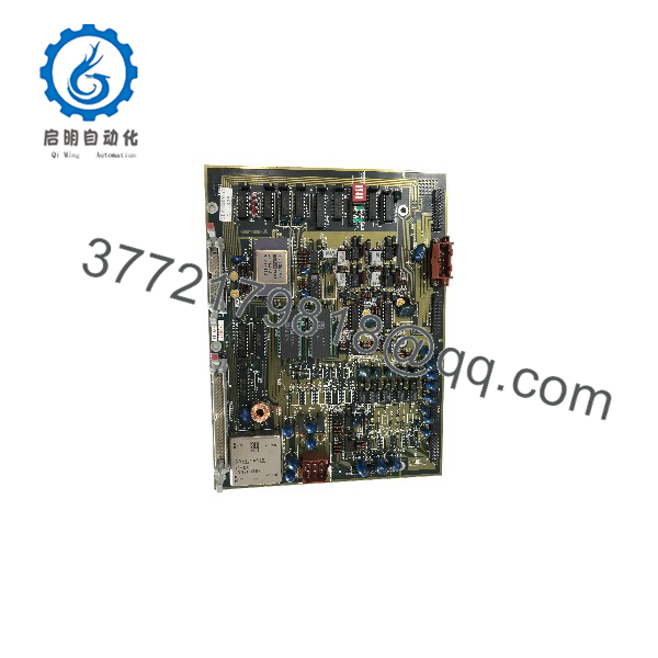
KBA-00650 4S007-320-A LC-SIG4
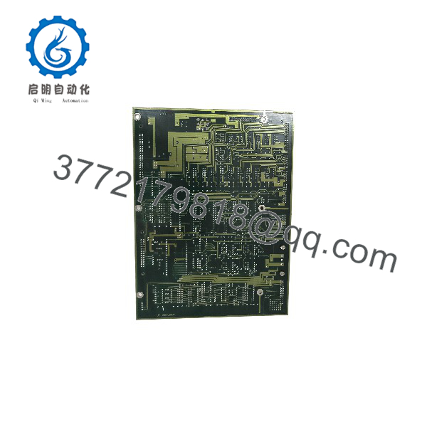
KBA-00650 4S007-320-A LC-SIG4
Installation & Configuration Guide
1.Pre-Installation Preparation:Prerequisite & Safety Prep.
Implement full lock-out/tag-out (LOTO) protocols on the host machine control cabinet. Put on a grounded ESD wrist strap before handling the PCB assembly to avoid static damage to sensitive semiconductor devices. Carefully photograph the terminal block connections, DIP switch layouts, and jumper positions on the original card prior to removal.
2.Module Removal:Board Disconnection.
Unplug external field wiring headers and interface cables by releasing their locking latches; do not pull directly on the wires. Loosen the card retainers or mounting screws on the chassis frame. Carefully slide the board straight out along the guide rails to avoid flexing the PCB or bending edge connector contact pins.
3.Configuration and Mechanical Seating:Hardware Match & Mounting.
Verify that all jumpers, DIP switches, and revision codes on the new KBA-00650 4S007-320-A LC-SIG4 board match the outgoing card exactly. Align the replacement module with the chassis guide slots and slide it smoothly into position until the backplane contacts engage fully. Secure all mounting screws and reconnect wiring harnesses.
4.Power-On & Diagnostic Testing:System Validation.
Restore main cabinet power. Observe the board power and status LEDs to confirm normal boot-up behavior and verify that no error flags lock on. Run system diagnostics from the main control interface to confirm signal transmission integrity and loop calibration accuracy.
Firmware/Software Versions & Upgrade Notes
- Revision Code Match: Verify that the 4S007-320-A revision mark matches your existing controller documentation to prevent hardware timing mismatches or pinout variations across board generations.
- Compatibility Requirements: The LC-SIG4 interface board relies on physical circuit matching with the host processor card. Confirm that system firmware and parameters match the designated hardware revision index.
- Firmware Modification Hazard: Do not attempt firmware modifications or re-flashing procedures during a field hardware swap. Mismatches between system software profiles and signal board hardware revisions can cause protocol timeouts, signal drops, or unexpected machine stops.
Frequently Asked Questions (FAQ)
What makes New Surplus significantly better than buying a refurbished KBA-00650 board?
Refurbished circuit boards often undergo solder rework and exposure to thermal cycling, leaving micro-cracks or weakened trace connections that can fail prematurely under industrial vibrations. Our New Surplus KBA-00650 4S007-320-A LC- boards are factory-fresh, uninstalled original units, offering maximum component lifespan and zero risk of hidden thermal stress degradation.
How do you verify that this PCB is genuine and unused?
Every unit passes a rigorous multi-point Quality Control inspection protocol. We verify original OEM markings, inspect backplane connector pins for zero insertion wear, verify clean solder joints with no rework, and store all modules in conductive ESD-safe packaging. A full QC inspection certificate is provided with shipment.
Does the 4S007-320-A require special software calibration upon installation?
Generally, no software calibration is required for a direct hardware swap, provided the DIP switch and jumper settings on the new LC- board are copied exactly from the original board. The central processor will automatically interface with the signal channels upon power-up.
What should I do if the revision letter on my old board differs slightly from 4S007-320-A?
In industrial hardware, minor letter revisions (such as -A vs -B) usually indicate minor component layout optimizations while maintaining backward compatibility. However, you should cross-reference the pinout diagrams and jumper tables in your machine manual or contact our technical team to verify exact drop-in compatibility before installation.
What warranty is included with this New Surplus board?
We back the 4S007-320-A LC- signal interface board with a full 1-year functional warranty. Should any hardware issue occur under standard operational conditions within 12 months, we provide an immediate unit replacement or full refund to protect your plant operating budget.