
 WhatsApp: +86 16626708626
 Email:
  Phone: +86 16626708626
Description
Key Technical Specifications
| Parameter | Value |
|---|---|
| Manufacturer Branding | Kollmorgen, Seidel, or Procon PAS Elektronik; verify actual unit label |
| Part Number | 60WKS-M240/22 |
| Common Suffix Variants | 60WKS-M240/22-PB, -PO, and -KPT; suffix must be matched before purchase |
| Series | 60WKS Analog Servo Amplifier Series |
| Product Type | Analog servo amplifier / servo drive |
| Rated DC Link Voltage | 240 VDC |
| Three-Phase Input Supply | 60–172 V AC, 50/60 Hz, ±10%; verify against the actual nameplate |
| Installed Load Rating | 3.7 kVA |
| Rated Output Current | 22 A RMS |
| Peak Output Current | 50 A |
| Ballast/Regenerative Circuit Continuous Power | 135 W |
| Ballast/Regenerative Circuit Pulse Power | 5.4 kW |
| Feedback / Motor Application | Verify the exact motor and feedback interface; listings differ by variant |
| Output Protections | Motor terminal short-circuit and earth-fault protection reported for the -PO variant |
| Motor Thermal Monitoring | Motor-temperature monitoring reported for the -PO variant |
| Enclosure Protection | IP00; install inside a suitable electrical enclosure |
| Environmental Classification | Pollution Degree 2 application per EN 60204 / EN 50178, reported for -PO variant |
| Lifecycle Status | Retired / obsolete analog servo-drive platform |
The supplied model is 60WKS-M24022, commonly formatted as 60WKS-M240/22. The available sources identify the family as a 240 VDC-link analog servo amplifier rated at 22 A RMS and 50 A peak, with a 3.7 kVA load rating and a 135 W continuous / 5.4 kW pulse ballast circuit. The market also shows several suffix variants. Do not install a -PB, -PO, or -KPT unit interchangeably until you verify the exact motor interface, connector layout, feedback requirements, firmware or board version, and application wiring.
Product Introduction
The Kollmorgen Seidel 60WKS-M240/22 is a legacy analog servo amplifier that converts a low-level motion command into controlled motor current for industrial positioning axes. It is used in equipment such as packaging machines, handling systems, printing/converting equipment, assembly machinery, and other systems built around older analog servo-control architectures.
This amplifier has a 240 VDC link, 22 A rated output current, and 50 A peak capability. It requires a properly matched motor, feedback device, power supply, regenerative braking arrangement, control interface, and tuning configuration. Confirm the complete suffix and all terminal assignments before ordering; a similarly named 60WKS drive can have an application-critical wiring or option difference.
Troubleshooting Quick Reference
| Symptom | Possible Cause | Relevance to This Part | Quick Check Method | Recommendation |
|---|---|---|---|---|
| Drive has no LEDs or no enable response | Missing three-phase supply, missing 24 V control supply, open fuse, failed power section, emergency stop active | ⚠️ Medium | Measure the specified AC input phases and auxiliary 24 V DC control supply at the drive terminals using the actual wiring diagram | Verify all supply rails, fuses, and safety-chain status before replacing the amplifier |
| Drive faults on undervoltage | Low AC supply, missing phase, weak transformer, loose terminal, excessive inrush/load | ❌ Low | Measure phase-to-phase voltage at the drive under commanded operation; inspect fuses, contactor contacts, and transformer output | Correct upstream power issues first. Do not replace the drive for an external supply fault |
| Drive faults on overvoltage during deceleration | Deceleration too short, ballast resistor open, ballast resistor wrong value, regenerative load too high | ⚠️ Medium | Compare DC-link behavior and fault timing during deceleration; with power isolated, check ballast-resistor continuity and wiring | Increase deceleration time or restore the correct braking circuit before replacing the drive |
| Motor does not move but drive enables | Zero analog command, inhibit active, broken motor lead, incorrect enable wiring, brake engaged, drive output fault | ⚠️ Medium | Confirm the command signal at the analog input with a meter or oscilloscope; check motor-brake voltage and output status | Verify command, enable, and brake circuits before condemning the drive |
| Immediate overcurrent or short-circuit fault | Shorted motor cable, motor winding fault, failed output transistor stage, incorrect motor wiring | ✅ High | Power down, disconnect the motor leads, and perform OEM-approved motor/cable insulation and winding checks; retest only per the drive manual | Isolate whether the fault follows the motor/cable or stays with the amplifier before replacement |
| Axis jitters, hunts, or vibrates at standstill | Incorrect gain/offset adjustment, feedback noise, loose coupling, wrong feedback polarity, grounding issue | ⚠️ Medium | Check analog command noise, tach/encoder feedback stability, grounding, shield connections, and mechanical coupling | Restore documented trim settings. Do not turn potentiometers randomly without recording original positions |
| Motor runs away or moves in the wrong direction | Reversed analog command polarity, feedback polarity error, incorrect motor phase sequence, parameter/trim mismatch | ✅ High | Command a very low-speed jog with axis mechanically safe; compare command polarity and actual direction | Stop immediately if the axis accelerates unexpectedly. Verify polarity and feedback wiring before further testing |
| Motor overheats while load is normal | Incorrect current limit, poor servo tuning, motor mismatch, brake drag, failed motor feedback | ⚠️ Medium | Trend motor current and case temperature; compare current demand with a known-good axis or motor data | Check matching and tuning. Persistent excessive current can damage both motor and amplifier |
| Drive overheats | Failed fan, blocked airflow, high cabinet temperature, overcurrent, poor heatsink contact | ✅ High | Inspect fan operation, heatsink cleanliness, enclosure temperature, and output current during duty cycle | Correct cooling and load conditions. Replace only if thermal trips persist at valid load and ambient conditions |
| Replacement amplifier does not communicate or operate correctly | Wrong suffix, connector/pinout mismatch, incompatible feedback, analog scaling mismatch, missing external option | ✅ High | Compare every label, terminal strip, connector, board revision, external resistor, and interface cable with the removed unit | Do not force a near-match. Obtain the exact suffix or a documented retrofit solution |
❗ Do not adjust gain, offset, tach, current-limit, or compensation potentiometers “until it works.” On analog servo systems, undocumented trim changes can turn a minor feedback problem into a runaway axis or repeated motor overcurrent fault. Take close photographs of every adjustment and terminal before removal.
The ballast circuit is another frequent trap. This drive family is reported with 135 W continuous and 5.4 kW pulse braking capability. A failed or incorrect braking resistor can create DC-bus overvoltage faults that look like drive failure. Check the resistor, wiring, deceleration profile, and mechanical load before replacing the amplifier.
If you need technical help, provide the exact suffix on the nameplate, LED/fault state, supply-voltage readings, motor part number, feedback type, brake-resistor label, control-terminal photos, and a video of the fault sequence.
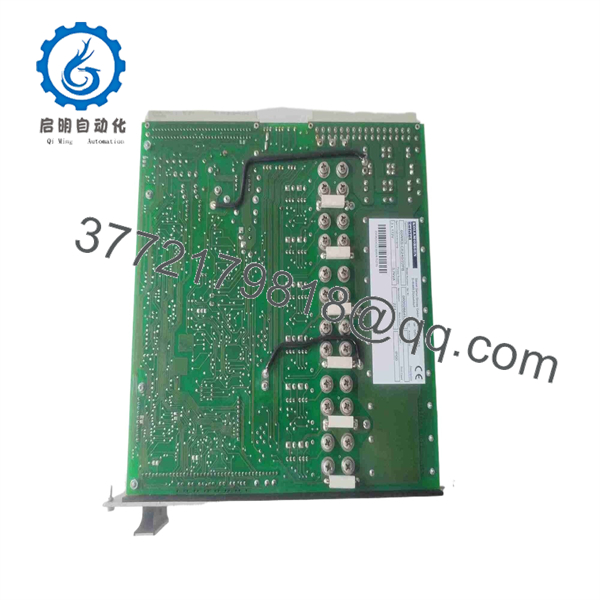
60WKS-M240/22
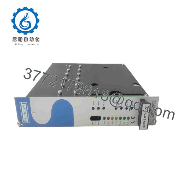
60WKS-M240/22
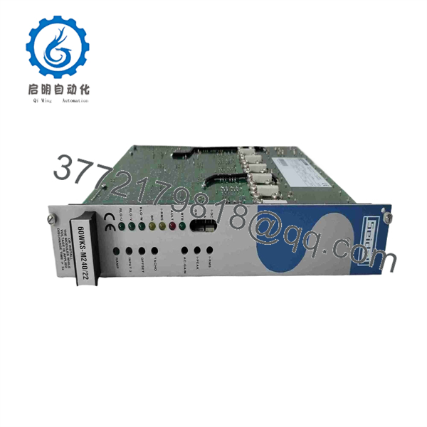
60WKS-M240/22
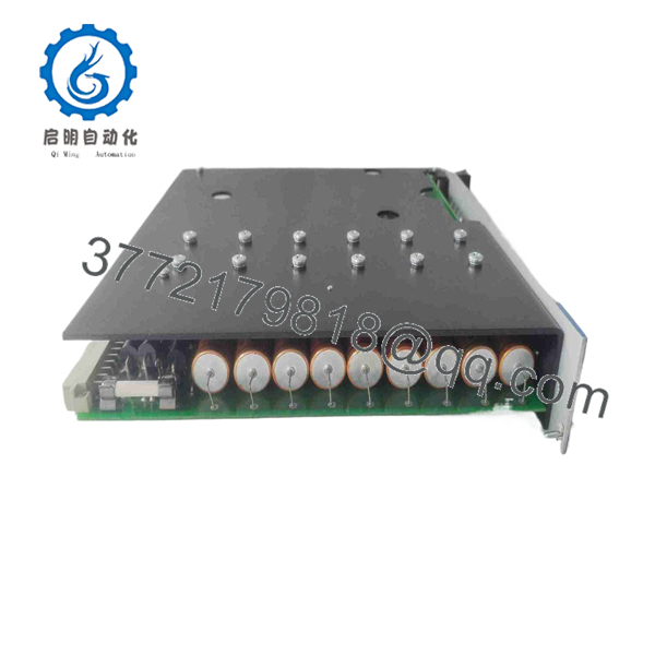
60WKS-M240/22
Frequently Asked Questions
What is the 60WKS-M240/22?
The 60WKS-M240/22 is a legacy analog servo amplifier associated with Kollmorgen, Seidel, and some Procon-branded inventory. It drives a matched servo motor from an analog motion command and is commonly identified with a 240 VDC link, 22 A RMS output rating, 50 A peak current, and 3.7 kVA installed-load rating.
Is 60WKS-/22 the same as 60WKS-/22-PB or 60WKS-/22-PO?
Not automatically. -PB, -PO, and -KPT appear in available market listings and may identify mechanical, connector, control, feedback, braking, or option differences. The base electrical ratings can be similar, but a one-letter suffix mismatch can stop an axis from enabling or create a wiring problem. Order the complete suffix shown on the failed drive unless engineering has validated the substitute.
What input power does this servo amplifier require?
The available 60WKS-/22 data identifies a three-phase 60–172 V AC, 50/60 Hz supply with a ±10% tolerance and a 240 VDC nominal internal DC link. This is not the same as a standard 380–480 V AC industrial VFD input. Confirm the exact nameplate, transformer secondary voltage, fuse size, and wiring diagram before connecting power.
Can I use this amplifier with any 22 A servo motor?
No. Output current alone does not establish compatibility. Match the motor voltage constant, winding resistance and inductance, continuous and peak current, feedback device, temperature sensor, brake circuit, mechanical load, and the amplifier’s control mode. Some available references associate 60WKS variants with Kollmorgen SM-series brushless synchronous motors, but verify that statement against the exact suffix and installed system.
Can I hot-swap a 60WKS servo amplifier?
No. Isolate all incoming power, lock out the machine, allow the DC link to discharge for the period specified by the equipment documentation, and verify that hazardous voltage is absent before handling the amplifier. The 240 VDC link and braking circuit can retain energy after input power is removed. Do not rely on extinguished LEDs as proof that the bus is discharged.
Why does the drive fault only during deceleration?
The usual cause is regeneration: the motor returns energy to the DC link while slowing down. If the deceleration ramp is too aggressive, the ballast resistor is disconnected, the resistor is incorrect, or the braking circuit has failed, the DC link can rise until the drive trips on overvoltage. Check the braking resistor and wiring with power removed, then compare deceleration settings with the original drive configuration.
Is this model obsolete, and what should I verify before buying?
Yes. The 60WKS analog servo amplifier family is described as retired. Inventory is generally New Surplus, used, refurbished, or repair-channel stock. Before purchase, require clear photos of the complete nameplate, suffix, terminals, connectors, board revision, braking-resistor interface, and any option boards. Verify physical stock, condition, lead time, warranty, motor compatibility, and whether the supplier has tested the unit at the required supply voltage.
Is New Surplus preferable to Refurbished?
New Surplus is unused original inventory and is often preferred if the unit has been stored correctly, shows no corrosion or capacitor leakage, and has complete labels and intact connectors. However, storage age matters for power electronics. Refurbished stock can be appropriate when the supplier documents component inspection, controlled power-up, motor test, load test, protection checks, thermal run, and warranty coverage. Ask directly whether aged electrolytic capacitors were inspected or replaced during refurbishment.
What supplier testing should I request?
For New Original / New Surplus stock, request source traceability, exact label and suffix verification, inspection for corrosion, rework marks, damaged terminals, fan condition, capacitor-condition screening, ESD-safe packaging, and actual unit photographs.
For Refurbished stock, request testing on a compatible three-phase supply and a matched servo motor or dynamometer setup. The report should document power-up, DC-link voltage, enable/inhibit operation, analog command response, output-current measurement, feedback recognition, direction check, motor-temperature input where used, short-circuit and earth-fault protection, braking-circuit behavior, fan operation, thermal stability during a continuous run, and final QC sign-off. Test photos and video should be available upon request.



