
 WhatsApp: +86 16626708626
 Email:
  Phone: +86 16626708626
Description
Key Technical Specifications
| Parameter | Value |
|---|---|
| Manufacturer | LAM Research |
| Part Number | 810-099175-011 |
| Board Type | VIOP Phase III PCB |
| Series | VIOP Phase III |
| Known Revisions | Rev A, Rev B |
| Equipment Application | LAM Research semiconductor processing equipment |
| Documented Tool | 2300 Versys Kiyo45 |
| Documented PM Function | VIOP B/D Step Driver |
| Wafer Platform in Reference Configuration | 12 in |
| Equipment Vintage in Reference Configuration | 2010 |
| Board Status in Inventory Record | Used |
| Electrical Input Voltage | Not verified from an OEM datasheet |
| Communication Interface | Not verified from an OEM datasheet |
| Dimensions | Not verified from an OEM datasheet |
| Weight | Not verified from an OEM datasheet |
| Firmware | Not verified |
A particularly useful equipment configuration record identifies 810-099175-011 as the “VIOP B/D Step Driver” in a Lam Research 2300 Versys Kiyo45 configuration.
The LNS Semiconductor inventory record separately lists 810-099175-011 Rev B and Rev A, both as VIOP, PHASE 3 and both in used condition.
Procurement note: Some reseller pages publish detailed electrical specifications for this part, but those specifications are not corroborated by the available equipment documentation. They should not be treated as OEM specifications without a matching Lam Research service manual or board-level drawing.
Product Introduction
The LAM Research 810-099175-011 is a VIOP Phase III printed circuit board used in Lam semiconductor-processing equipment. Available parts inventories identify it specifically as a VIOP Phase III board, while an equipment configuration for a 2300 Versys Kiyo45 identifies the board as the VIOP board/step driver.
Revision control is important with this part. Both Rev A and Rev B examples are documented, so the replacement should be compared against the installed board before installation. Do not assume that every 810-099175-011 revision is interchangeable without confirming the equipment configuration and board documentation.
Installation & Configuration Guide
Stage 1: Pre-Installation Preparation
Estimated time: 10 minutes
⚠️ Safety First: Place the semiconductor-processing tool in its approved maintenance state. Follow the equipment-specific LAM Research shutdown procedure, isolate applicable energy sources, and complete site lockout/tagout requirements before removing the PCB.
Tools Required:
- ESD wrist strap
- ESD-safe work surface
- Appropriate Phillips/flat-head screwdrivers
- Multimeter
- Connector labels
- Smartphone or camera
- Equipment service documentation
Data Backup:
- Record the complete part number: 810-099175-011.
- Photograph the installed board’s revision marking.
- Record whether the installed board is Rev A, Rev B, or another marking.
- Photograph every connector before removal.
- Photograph jumpers, switches, termination links, or configuration plugs.
- Record cable routing.
- Record the equipment model, chamber/PM position, and board location.
- Keep the original board until the replacement has completed functional verification.
⚠️ Revision matters. Public inventory documentation identifies both Rev A and Rev B for 810-099175-011. Treat the revision as part of the replacement identification, not as an incidental marking.
Stage 2: Removing the Old Module
Estimated time: 5–10 minutes
- Verify that the tool has reached the required maintenance state.
- Open the applicable electronics enclosure or VIOP access area.
- Photograph the board and connector layout before touching the wiring.
- Label connectors that could be confused during reinstallation.
- Release the PCB retaining hardware.
- Disconnect cables using the connector bodies rather than pulling on wires.
- Remove the board using the manufacturer’s approved extraction method.
- Place the removed board on an ESD-safe surface.
- Inspect the mating connectors for bent contacts, contamination, oxidation, or mechanical damage.
⚠️ Do not discard the old PCB immediately. If the replacement produces an unexpected initialization or communication fault, the original board provides the reference for revision, connector placement, and physical configuration.
Stage 3: Installing the New Module
Estimated time: 5–10 minutes
- Verify the replacement marking is 810-099175-011.
- Compare the revision with the removed board.
- Compare PCB layout, connectors, mounting holes, and component population.
- Put on the grounded ESD wrist strap.
- Inspect the replacement board for shipping damage.
- Verify all configuration links against the original board.
- Install the PCB in the correct VIOP position.
- Secure the retaining hardware according to the equipment service procedure.
- Reconnect each cable using the photographs taken during removal.
- Confirm that connectors are fully seated.
Self-Checklist:
- Part number matches
- Revision checked
- Board orientation correct
- Connector positions verified
- Configuration links checked
- Mounting hardware secured
- No cable is trapped or pinched
- ESD precautions maintained
Stage 4: Power-On & Testing
Estimated time: 10–15 minutes
- Perform a final visual inspection before applying power.
- Check for loose hardware or foreign objects inside the enclosure.
- Restore power according to the equipment procedure.
- Observe board and system status indicators.
- Check the equipment controller for board initialization faults.
- Verify the VIOP subsystem communicates correctly with the control system.
- Execute the applicable equipment diagnostic sequence.
- Test the associated motion/stepper function only under the approved service procedure.
- Confirm that no new interlock or subsystem alarms are generated.
- Return the equipment to normal operation only after the complete functional check passes.
⚠️ Do not substitute generic PCB test criteria for the equipment manufacturer’s procedure. The available public documentation establishes the board as a VIOP Phase III board and, in one configuration, a VIOP step-driver board, but it does not establish the complete electrical pinout or commissioning sequence.
Practical Replacement Pitfalls
❗ 1. Revision mismatch
The LAM parts inventory identifies both Rev A and Rev B versions of 810-099175-011. Do not order solely from the base part number if the equipment documentation specifies a board revision.
❗ 2. Confusing the board with other VIOP variants
LAM equipment suppliers also list nearby VIOP part numbers such as 810-099175-009 and other VIOP boards. Verify every digit of the part number before purchase.
❗ 3. Assuming published specifications are OEM data
Several reseller pages give detailed voltage, temperature, interface, and dimensional specifications, but these specifications conflict with one another. For example, one source describes the board as a stepper interface controller, while another describes it as an analog voltage I/O processor.
For procurement and maintenance documentation, use the physical board marking and LAM equipment documentation as the controlling references.
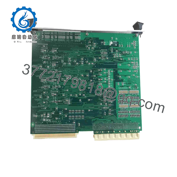
810-099175-011
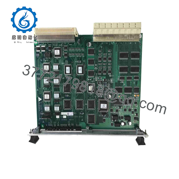
810-099175-011
Frequently Asked Questions (FAQ)
Can the 810-099175-011 be used as a direct replacement?
It can be a replacement candidate when the installed equipment specifically calls for 810-099175-011, but the board revision and equipment configuration should be verified first. Public records document both Rev A and Rev B.
What equipment uses 810-099175-011?
A documented configuration for a LAM Research 2300 Versys Kiyo45 identifies 810-099175-011 as the VIOP B/D Step Driver. This provides concrete evidence of use in that equipment configuration, but it should not be interpreted as proof that every Versys or Kiyo configuration uses the same revision.
Is 810-099175-011 a VIOP Phase III board?
Yes. Multiple industrial-equipment inventories identify it as VIOP Phase III, and a LAM parts inventory specifically lists 810-099175-011 as “VIOP PHASE III REV B.”
Are Rev A and Rev B interchangeable?
That cannot be established from the available documentation. Both revisions exist, but the public inventory record does not provide an engineering change notice or compatibility matrix. Match the revision to the installed equipment documentation before substituting one for another.
Is this part new or used?
Condition depends on the supplier. The LNS Semiconductor inventory explicitly records both Rev A and Rev B examples as Used. Another listing offers a pre-owned 810-099175-011 as-is and untested. Therefore, buyers should request the actual board photographs, revision marking, test status, and warranty terms before purchasing.
Can this PCB be hot-swapped?
Do not assume so. The available sources do not establish an approved hot-swap procedure for 810-099175-011. Treat it as a powered-down board replacement unless the specific LAM equipment service documentation explicitly permits live replacement.
What should I verify before ordering?
At minimum, provide the supplier with:
- 810-099175-011
- Installed board revision
- LAM equipment model
- Chamber/PM position
- Clear photographs of the board label
- Connector layout
- Required condition: new surplus, tested used, or refurbished
This is particularly important because public listings contain conflicting descriptions and specifications for this part. The strongest cross-source identification is LAM Research VIOP Phase III, with documented Rev A/Rev B variants and use as a VIOP step-driver board in at least one 2300 Versys Kiyo45 configuration.



