
 WhatsApp: +86 16626708626
 Email:
  Phone: +86 16626708626
Description
Key Technical Specifications
- Manufacturer: LAM Research
- Manufacturer Part Number: 810-801237-021
- Associated Assembly Marking: 855-801237-021; verify on the installed board
- Product Identification: PCB Assembly, Stepper Driver Interface
- Product Type: Semiconductor equipment motion-control interface board
- Primary Function: Routes motion commands, drive-enable signals, fault status, and position-feedback signals between the LAM tool controller and compatible stepper-drive hardware
- Typical Application: Internal motion-control electronics in LAM Research semiconductor process equipment
- Installation Type: Internal electronics-rack or motion-control chassis PCB assembly
- Command Signals: Stepper motor command and drive-interface signals; exact electrical standard and connector assignment require tool-specific verification
- Feedback Signals: Drive status, fault, limit, and position-related signals; exact encoder or resolver implementation not publicly verified
- Supply Requirements: Not publicly verified from an OEM datasheet; confirm rack voltage rails, current requirements, grounding, and connector pinout using the LAM electrical drawing
- Revision Control: Revision-sensitive part; document PCB revision, component labels, jumpers, switches, and connector positions before replacement
- Handling Requirement: ESD-controlled handling, anti-static packaging, and proper grounding required
- Lifecycle Status: Legacy/obsolete semiconductor-tool spare part; stock may be limited to surplus, used, or tested-refurbished inventory
Public listings consistently identify 810-801237-021 as a LAM Research Stepper Driver Interface PCB or board assembly. Some supplier pages make detailed claims regarding voltage, tool platforms, axis count, protocols, and drive ratings, but those claims are not independently supported by publicly available LAM OEM documentation. Verify all electrical and compatibility details against the removed board and the exact tool schematic before installation.
Product Introduction
The LAM Research 810-801237-021 is a Stepper Driver Interface PCB Assembly for compatible LAM semiconductor manufacturing equipment. It supports the signal path between the tool’s motion controller and the stepper-drive system, carrying motion command, enable, status, fault, and position-related signals for machine mechanisms.
This is an exact replacement spare for motion-control cabinets, not a universal stepper driver. Buyers typically source 810-801237-021 when a mechanical axis will not enable, loses commanded motion, faults intermittently, or reports persistent drive-interface errors. Match the full part number, associated assembly marking, connector layout, and installed revision before ordering.
Troubleshooting Quick Reference
| Symptom | Possible Cause | Relevance to this Part | Quick Check Method | Recommendation |
|---|---|---|---|---|
| Stepper axis has no movement after a motion command | Open safety chain, missing drive supply, failed motor driver, broken motor cable, missing controller output | ❌ Low to medium | Verify that the tool is in an enabled and safe operating state. Check drive supply rails at documented test points and review servo/stepper-drive status indicators. | Check power, safety interlocks, and the downstream motor driver before replacing the interface PCB. |
| Axis reports “Drive Not Ready” or “Enable Missing” | Safety relay open, drive fault, defective enable path, loose interface connector, failed board channel | ✅ Medium | Review the exact diagnostic code. Trace the enable signal from the controller to the board connector and then to the drive using the LAM electrical drawing. | Replace the board only when the controller and external drive are proven healthy but enable fails across the board. |
| Axis moves in one direction only | Incorrect wiring, failed drive output stage, damaged limit circuit, command-signal channel fault | ✅ Medium | Inspect limit-switch status, motion cable condition, and controller output diagnostics. Compare step/direction signals with a known-good axis if the tool design permits. | Do not assume the board failed. Verify limits, cable continuity, and the motor driver first. |
| Axis stops or faults during homing | Failed home sensor, encoder/position-feedback fault, mechanical obstruction, cable intermittency, interface-board signal loss | ✅ Medium | Check home-sensor LEDs, mechanical travel, actuator condition, and feedback cable integrity. Capture diagnostic logs before cycling tool power. | Correct sensor and mechanical issues first. Replace the board if known-good feedback reaches the board but does not return to the controller. |
| Multiple motion axes fail together | Common power supply loss, rack backplane fault, controller issue, interface-board failure | ✅ High | Identify whether affected axes share 810-801237-021. Measure documented rack supply rails under load and inspect board seating and edge contacts with power removed. | A board fault is possible, but shared supply and backplane issues must be ruled out before replacement. |
| New board causes immediate motion or communication alarms | Incorrect board revision, jumper mismatch, wrong connector position, incompatible tool configuration | ✅ High | Photograph the original board before removal. Match all labels, revision codes, jumper locations, cable identifiers, and connector keying on the replacement. | Stop commissioning. Reinstall the original if safe, then verify compatibility using the exact LAM tool documentation. |
| Motion faults occur only after the cabinet warms up | Thermal drift, weak power supply, connector resistance, aging drive electronics, marginal interface component | ✅ Medium | Record the time to failure and cabinet temperature. Inspect for overheated connectors, discolored PCB areas, and unstable supply rails under normal machine load. | Correct cooling and supply problems first. Replace the board only if the fault follows the PCB after controlled testing. |
| Board has corrosion, burned components, or damaged connectors | Overvoltage, external short, contamination, liquid ingress, ESD damage | ✅ High | Apply lockout/tagout, then inspect both sides of the board and mating connectors under magnification. Check associated harnesses before fitting a replacement. | Replace the damaged board and find the external cause before energizing the replacement. |
❗ Firmware and revision mismatch: A stepper interface board can fit in the rack and still fail to communicate correctly with the installed controller. I have seen a tech lose two days to a “Communication Timeout” after fitting a visually identical revision. Capture every board marking before removal.
❗ DIP switch and jumper settings: Take clear photographs of the original unit, including every jumper, switch, ribbon cable, and connector label. Seriously. Factory defaults may not match your axis addressing, limit configuration, or signal polarity.
❗ Connector and pinout traps: Do not wire from memory. Motion systems may carry low-level command signals near motor-drive and interlock wiring. A similar-looking connector can have a different pinout, shield termination, or keying arrangement.
❗ Power draw and supply health: Check the complete rack power budget and verify supply rails while the axis is commanded to move. A weak supply can create intermittent enable faults that look like a failed interface board. Leave a 20% current margin where the system design allows.
❗ ESD damage happens before startup: Use an ESD-safe bench and a grounded wrist strap. I have watched someone handle an expensive motion card during dry weather, reinstall it, and get immediate faults on power-up. Use the strap.
Keep these checks in mind and you will save yourself 90% of typical rework time. If the fault remains unclear, contact technical support with photos of both board sides, all labels, motion alarms, drive LED status, and tool diagnostic logs.
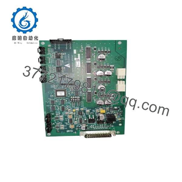
810-801237-021
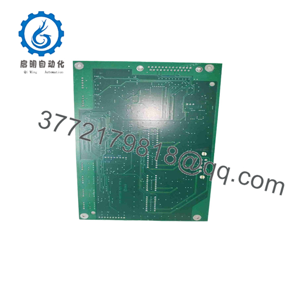
810-801237-021
Frequently Asked Questions
What is the LAM 810-801237-021 used for?
The LAM Research 810-801237-021 is identified in public equipment listings as a Stepper Driver Interface PCB. It is used in the internal motion-control architecture of compatible LAM semiconductor equipment, connecting controller-level motion signals with stepper-drive hardware and related status or feedback circuits.
Is this a complete stepper motor drive?
Not necessarily. The available descriptions call it a Stepper Driver Interface board, which indicates it likely serves as the connection and signal-conditioning layer between the system controller and the drive hardware. Do not assume it provides motor power, accepts a standard stepper motor directly, or replaces a separate amplifier. Confirm the installed tool schematic and the board’s connector labels before ordering.
Can I hot-swap 810-801237-021?
No. Treat the board as non-hot-swappable unless your specific LAM tool manual explicitly states otherwise. Pulling a motion interface board while energized can create drive faults, corrupt feedback signals, damage rack connections, or place a moving mechanism in an unsafe state. Shut down the tool under the approved maintenance procedure, apply lockout/tagout, and use ESD controls.
How do I know the stepper interface board is the problem?
First verify the safety chain, controller alarms, rack supplies, motor-driver status, motor wiring, home and limit sensors, feedback devices, and mechanical freedom of movement. The board becomes the likely fault when a valid controller command arrives at its input but does not pass to the drive, or when healthy drive feedback reaches the board but does not return to the controller. A repeatable fault that follows the board is the strongest field confirmation.
Will I lose motion settings if I replace the board?
The main motion program and tool configuration usually reside in a controller or host system, not necessarily on the interface board. Still, configuration can depend on board revision, jumpers, switches, and cable assignments. Before removal, photograph every setting and connector, save diagnostic records, and record the full part number and revision markings. Never rely on memory for a legacy motion rack.
Is 810-801237-021 obsolete?
Treat it as a legacy LAM semiconductor-equipment spare. Public listings show surplus and used-market availability, including listings for new and parts-only condition, which means condition and test scope can vary substantially. Confirm the actual item condition, stock quantity, board revision, photographs, lead time, and warranty before issuing a purchase order.
Why is a New Surplus board cheaper than an OEM replacement?
New Surplus inventory may come from unused maintenance spares, canceled equipment projects, tool decommissions, warehouse liquidations, or inventory held after a platform reaches end of life. The lower price is not automatically a problem. What matters is whether the seller discloses the condition, supplies clear label and connector photos, identifies the exact board revision, states the functional test performed, and provides written warranty terms.
What testing should I request before buying?
Request an inbound inspection covering board labels, connector condition, corrosion, scratches, missing components, rework evidence, and ESD-safe packaging. Ask for high-resolution photographs of both sides of the board and a test report if a compatible LAM motion rack is available. A meaningful functional test should verify power-up behavior, status indication, command and feedback paths, and stable operation under load. If the supplier cannot perform an in-rack test, they should say so clearly rather than represent the unit as fully tested.



