
 WhatsApp: +86 16626708626
 Email:
  Phone: +86 16626708626
Description
Key Technical Specifications
| Parameter | Value |
|---|---|
| Manufacturer | Lam Research |
| Part Number | 810-072906-005 |
| Alternate Format | 810072906005 |
| Product Type | Connector Backplane |
| PCB Type | Equipment interconnect/backplane assembly |
| Primary Function | Connector and signal interconnection |
| Application | Semiconductor manufacturing equipment |
| Manufacturer Family | Lam Research |
| Tool Compatibility | Tool-specific; verify equipment BOM |
| Power Rating | Not publicly verified |
| Supply Voltage | Not publicly verified |
| I/O Count | Not publicly verified |
| Connector Type | Tool-specific; verify physical board |
| Communication Protocol | Not publicly verified |
| Dimensions | Not reliably established from OEM documentation |
| Operating Temperature | Not publicly verified |
| Weight | Not reliably established from OEM documentation |
| Revision | Verify against installed board |
| Condition | New / Used / Refurbished availability reported |
The strongest current evidence identifies 810-072906-005 as a Lam Research Connector Backplane. An industrial inventory listing gives the exact part number and description, while a current eBay record also identifies the exact assembly as a Lam Research CONNECTOR BACKPLANE 810-072906-005.
There are conflicting secondary-market descriptions that call this part a “microprocessor control circuit,” “control board,” or even an RF matching network. Those descriptions are not consistent with the more specific connector-backplane identification and should not be used as verified specifications.
Procurement warning: I did not find a reliable public Lam Research datasheet establishing the exact connector pinout, voltage ratings, number of positions, or compatible tool models. Those details should be verified from the physical PCB and target-tool BOM rather than inferred.
Product Introduction
The Lam Research 810-072906-005 is a connector backplane assembly used within Lam Research semiconductor equipment. Its primary role is electrical interconnection between equipment modules, connectors, and associated wiring rather than standalone process control.
Because a backplane is dependent on the mechanical and electrical architecture of the host tool, exact connector arrangement and compatibility are critical. A visually similar Lam Research backplane should not be substituted solely because its dimensions or connector count appear comparable.
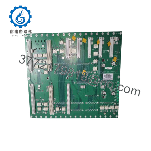
810-072906-005
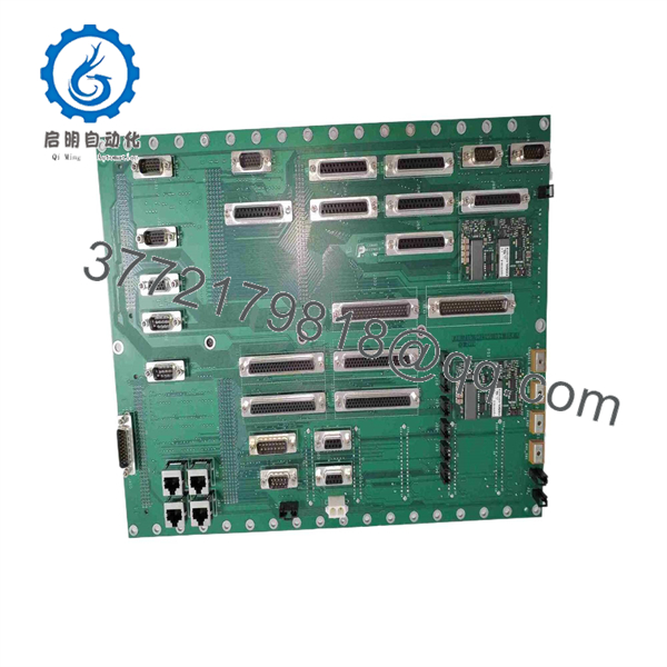
810-072906-005
Installation & Configuration Guide
Estimated replacement time: 30–60 minutes for an experienced semiconductor-equipment technician, excluding equipment qualification.
Stage 1: Pre-Installation Preparation
⚠️ Safety First
- Place the Lam Research tool in the approved maintenance state.
- Stop active wafer processing.
- Follow the equipment-specific shutdown procedure.
- Apply electrical LOTO and isolate applicable pneumatic, vacuum, RF, and process-gas energy.
- Verify stored energy has been removed.
- Follow the fab’s ESD and contamination-control requirements.
Tools Required
- ESD wrist strap
- Cleanroom gloves
- Precision screwdriver set
- Digital multimeter
- Connector labels
- Camera/smartphone
- Torque-controlled driver where specified
- Equipment configuration backup
Data Backup
Before removing the original backplane:
- Photograph the complete assembly.
- Record 810-072906-005.
- Record all revision markings.
- Photograph every connector.
- Photograph cable routing.
- Record the card/cabinet location.
- Identify connected modules.
- Record active equipment alarms.
⚠️ For a backplane, connector documentation is more important than software backup. Photograph every cable before disconnecting it.
Stage 2: Removing the Existing Backplane
- Confirm the equipment is in the approved maintenance state.
- Verify electrical isolation.
- Confirm stored energy has been discharged.
- Label every cable and connector.
- Disconnect cables by their connector bodies.
- Remove connected module hardware as required.
- Release the backplane mounting hardware.
- Remove the backplane without flexing the PCB.
- Place the removed board in an ESD-safe container.
Inspect:
- Connector contacts
- Backplane traces
- Mounting holes
- Cracked solder joints
- Heat discoloration
- Corrosion
- Contamination
- Damaged locking mechanisms
Estimated time: 15–25 minutes.
Stage 3: Installing the Replacement
- Verify the replacement marking reads 810-072906-005.
- Compare the revision against the removed unit.
- Compare all connector positions.
- Compare mounting-hole locations.
- Check the PCB for transport damage.
- Install the backplane without forcing connectors.
- Secure the mounting hardware.
- Reconnect every cable according to the photographs.
- Reinstall the associated modules.
- Verify connector locking mechanisms.
- Check grounding/bonding connections where applicable.
Critical Compatibility Check
Before power is restored:
- Exact part number confirmed
- Revision confirmed
- Connector layout matches
- Module positions match
- Cable routing matches
- No connector is offset by one position
- No bent contacts
- No foreign material on connectors
- Ground/bonding connections verified
⚠️ Do not force a mating connector. If a connector does not seat naturally, stop and verify the board revision and connector orientation.
Stage 4: Power-On & Testing
- Perform a complete visual inspection.
- Confirm no tools or foreign objects remain inside the equipment.
- Restore power according to the Lam Research procedure.
- Check for abnormal current draw or alarms.
- Verify the host controller recognizes all connected modules.
- Check communication with affected subsystems.
- Verify relevant sensor and actuator signals.
- Check interlocks.
- Run the approved service diagnostic.
- Perform the equipment dry-cycle test.
- Review diagnostic logs.
- Complete required tool/chamber qualification before production release.
⚠️ A backplane can appear physically correct while having an open trace, damaged connector contact, or revision mismatch. Functional verification should therefore be performed at the module level after installation.
Frequently Asked Questions (FAQ)
1. What is Lam Research 810-072906-005?
The strongest available identification is a Lam Research Connector Backplane. The exact part number is explicitly listed as a connector backplane in current industrial inventory and resale records.
2. Is 810-072906-005 a controller board?
It should not be treated as a conventional controller or PLC CPU based on the strongest evidence. Its documented aftermarket identification is Connector Backplane, meaning its principal function is electrical interconnection between modules and wiring.
3. What does a connector backplane do?
A backplane provides the physical and electrical interconnection between plug-in modules or assemblies. Depending on the equipment design, it can carry power, control signals, data, and other electrical interfaces.
The exact signal assignments for 810-072906-005 are not publicly verified, so specific voltage or communication claims should not be made without the Lam Research tool documentation.
4. Is 810-072906-005 an RF matching network?
One online listing incorrectly describes the part as a dual-frequency RF matching network. That description is inconsistent with multiple other records identifying the exact number as a connector backplane.
For procurement purposes, I would treat Connector Backplane as the defensible identification.
5. Can I substitute another Lam Research backplane?
Not without verification. The following must match:
- Complete part number
- Revision
- Connector arrangement
- Mechanical mounting
- Module positions
- Electrical routing
- Target Lam Research tool
A similar-looking backplane can have different pin assignments.
6. Is 810-072906-005 still available?
Yes. Current secondary-market records show this exact Lam Research part being offered as used/as-is, and other industrial suppliers list new or used inventory.
Availability and condition vary considerably, so procurement specifications should state the required condition and test evidence.
7. What should I request from a supplier?
For a production-critical Lam Research tool, request:
- Clear nameplate photograph
- Full 810-072906-005 part number
- PCB revision
- Front/rear PCB photographs
- Connector photographs
- Target tool compatibility
- New Original/New Surplus or Refurbished Tested condition
- Functional test report
- Warranty period
A supplier should also confirm that the unit is not a repaired board with undocumented connector or trace modifications.
8. What QC should be required for a used replacement?
At minimum, request visual inspection, connector/contact inspection, continuity testing where applicable, power-on verification in a compatible test setup, and documentation of the test results. For semiconductor-tool spares, ESD-safe packaging and traceability are also important.



