
 WhatsApp: +86 16626708626
 Email:
  Phone: +86 16626708626
Description
Key Technical Specifications
| Parameter | Specification |
| Manufacturer | Metso Automation / Valmet |
| Part / Assembly Number | IOP351 / 69230I351A |
| Module Type | Relay Digital Output Module |
| Contact Configuration | Form A / Form B Relays |
| Operating Logic Voltage | 24 V DC |
| Channel Count | Multi-channel discrete output array |
| Isolations | Galvanic isolation between field contacts and system bus |
| Status Indication | Front-panel LED diagnostic lights (Power, Status, Channel Active) |
| Physical Weight | ~0.90 kg to 0.95 kg (1.90 lbs) |
| Operating Temperature | 0°C to +60°C |
| Mounting Format | System rack / I/O base chassis insertion |
Product Introduction & Supply Chain Strategy
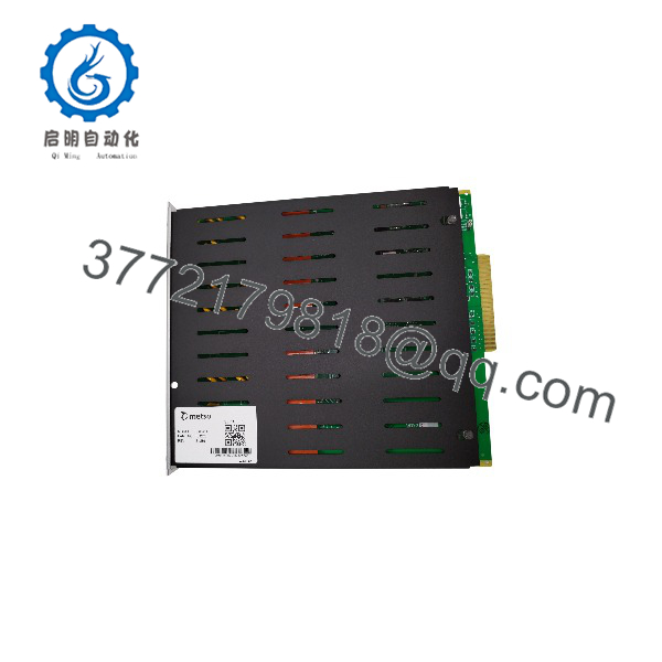
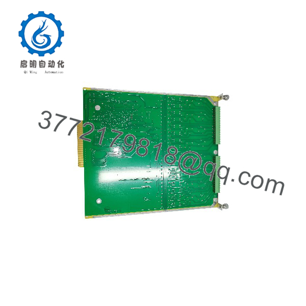
The Metso IOP351 is a high-density relay output module engineered for Metso process control architectures. It interfaces low-level controller logic with high-power field actuators, interlocks, solenoid valves, and motor starters across paper, power, and chemical processing facilities.
This product is a Brand New Surplus unit. It is not used, not pulled from a decommissioned plant, and not refurbished. All modules undergo rigorous quality verification to ensure OEM-level reliability.
Refurbished digital output modules frequently suffer from contact pitting, degraded coil windings, and invisible thermal fatigue on the backplane interface logic. Attempting to save a minimal amount on a used or repaired relay module creates an unacceptable risk of intermittent contact welding, false actuation, and emergency plant trips. Procuring genuine New Surplus inventory guarantees original OEM contact ratings and uncompromised dielectric isolation, lowering your Total Cost of Ownership (TCO) while securing critical spare parts for active legacy systems.
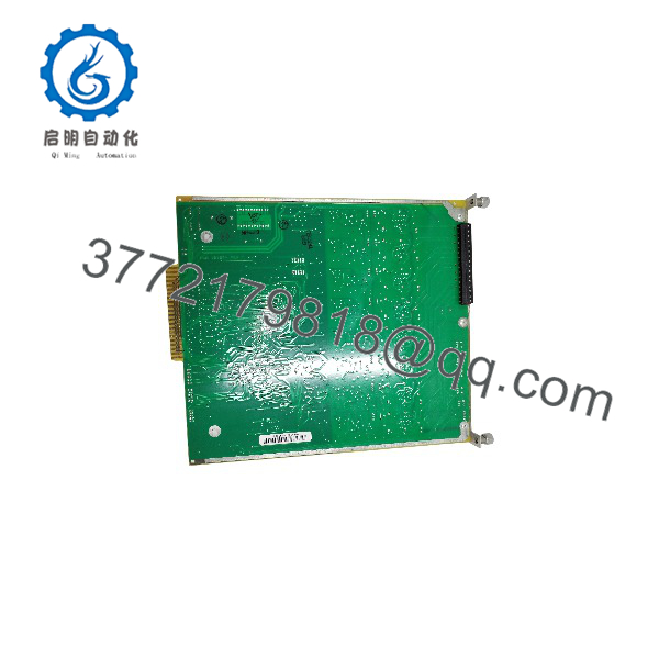
IOP320
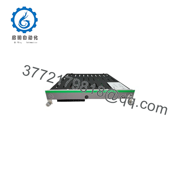
IOP320
Installation & Configuration Guide
Stage 1: Pre-Installation (Prep & Safety)
- Initiate Lock-Out/Tag-Out (LOTO) procedures on field devices wired to the IOP351 module terminal base.
- Put on an anti-static wrist strap and connect it to a verified panel ground point to prevent electrostatic discharge (ESD) damage.
- Record hardware revisions, jumper positions, and DIP switch settings on the existing module using photos and written documentation.
Stage 2: Removal
- Unplug field terminal blocks from the module base using two hands to avoid stressing field wiring.
- Unlatch top and bottom module retaining clips carefully.
- Pull the module straight outward along its guide rails to avoid bending or snapping the backplane connector pins.
Stage 3: Installation (Clone & Seat)
- Verify that all jumper contacts and address switches on the new IOP351 match the original hardware configuration precisely.
- Align the module card edges with the subrack guide rails.
- Push the module firmly into the chassis until the backplane connector seats completely, then engage top and bottom retaining latches.
- Reattach field terminal blocks, ensuring screws are torqued properly.
Stage 4: Power-On & Testing
- Measure the 24V DC bus voltage to confirm power supplies operate within tolerance before powering the subrack.
- Energize the rack and observe the front-panel status LEDs. The Power LED must illuminate solid green without red Error fault indications.
- Force output channels individually through controller diagnostic software to verify physical relay contact closure at the field terminals.
Firmware/Software Versions & Upgrade Notes
- System Compatibility: Ensure your controller base software supports the assembly revision of the IOP351 module (e.g., Assembly 181836).
- Backward Compatibility: Hardware revisions of the IOP351 maintain backward compatibility across classic Metso rack backplanes, but field contact ratings and relay bounce characteristics must match application parameters.
- Firmware Risks: Never flash or reload firmware on a live system chassis during production runs. Firmware mismatches between controller communications cards and local I/O interface racks can interrupt system scan cycles, leading to lost contact states or immediate fail-safe lockouts.
Frequently Asked Questions (FAQ)
Q: Is this Metso module truly brand new, or is it pulled from a working environment?
A: This unit is 100% genuine New Surplus. It has zero operational hours, zero wear on backplane connection pins, and was stored in ESD-safe conditions since manufacture. It is not pulled from a active site, repaired, or refurbished.
Q: Why should I choose New Surplus over a refurbished option?
A: Refurbished relay output cards carry hidden risks such as micro-welded contacts, degraded coil insulation, and dried-out board capacitors. A single relay failure on a critical trip circuit can cause tens of thousands of dollars in unplanned downtime. New Surplus provides original factory integrity at a fraction of current OEM lead times.
Q: How do you verify the quality of this module before shipment?
A: Every undergoes comprehensive bench inspection. We verify visual package condition, test backplane ground continuity, conduct power-on self-tests, and perform functional relay state switching checks under load before sealing the unit in heavy-duty ESD packaging.
Q: Is the Metso module still actively manufactured?
A: The series is marked as a legacy or discontinued module by the original manufacturer. Acquiring New Surplus units now allows plants to maintain buffer stock without risking re-engineering costs for system upgrades.
Q: What installation precautions should I take regarding DIP switches and jumpers?
A: Always duplicate the physical DIP switch and jumper arrangements from your existing module onto the new unit before inserting it into the rack. Incorrect addressing will prevent the I/O bus controller from recognizing the slot.
Q: What warranty coverage applies to this item?
A: Every New Surplus module includes a comprehensive 1-Year functional warranty against defect or operational failure, backed by complete QC test documentation.



