WhatsApp: +86 16626708626
 Email:
 Phone: +86 16626708626
Description
Key Technical Specifications
| Parameter | Value |
|---|---|
| Manufacturer | microsonic GmbH |
| Model | MIC+130/IU/TC |
| Housing | Cylindrical M30, nickel-plated brass sleeve |
| Operating range | 200–1,300 mm |
| Maximum range | 2,000 mm |
| Blind zone | 200 mm |
| Transducer frequency | 200 kHz |
| Measurement principle | Ultrasonic echo propagation time |
| Resolution | 0.18–0.57 mm, depending on analog window |
| Reproducibility | ±0.15% |
| Accuracy | ±1%, internal temperature compensation |
| Analog output | 1 × 4–20 mA or 0–10 V, rising/falling selectable |
| Supply voltage | 9–30 V DC, reverse-polarity protected |
| No-load current | ≤80 mA |
| Response time | 110 ms |
| Availability delay | <300 ms |
| Connection | 5-pin M12 initiator plug |
| Configuration | 2 push buttons, 3-digit LED display, TouchControl; LinkControl via LCA-2 |
| Indicators | 3-digit LED display and 2 three-color LEDs |
| Protection rating | IP67 per EN 60529 |
| Operating temperature | −25 to +70°C |
| Storage temperature | −40 to +85°C |
| Weight | 110 g |
Specifications are from the manufacturer datasheet for the MIC+130/IU/TC.
Product Introduction
The microsonic MIC+130/IU/TC is an M30 cylindrical ultrasonic distance sensor for non-contact measurement of level, position, height, width, and object presence. It measures from 200 to 1,300 mm and provides a selectable 4–20 mA or 0–10 V analog signal for PLC, DCS, and standalone control applications.
Its onboard TouchControl display and push buttons allow teach-in or numeric configuration without a laptop. Internal temperature compensation, synchronization/multiplex capability, IP67 protection, and a short-circuit-proof analog output make it a practical replacement for older ultrasonic sensors in washdown-prone or dusty production areas.
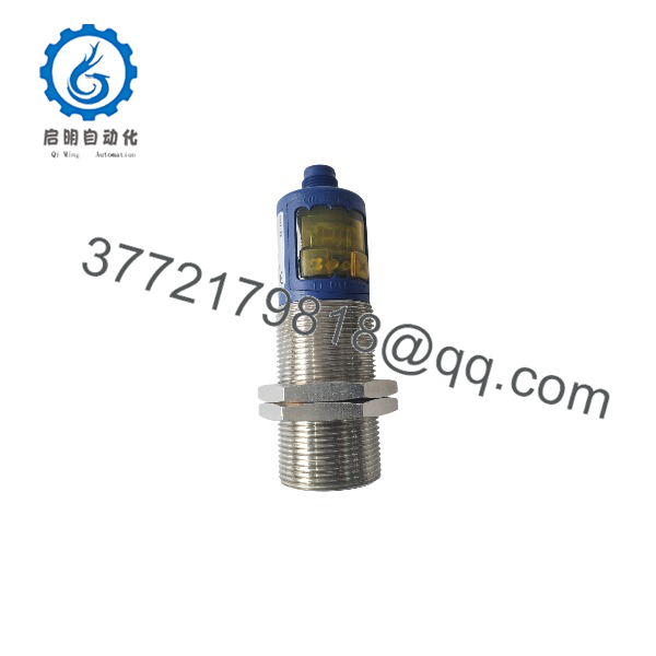
MIC+130/IU/TC
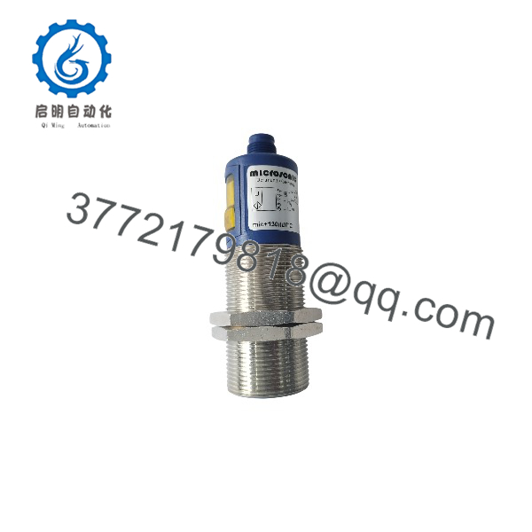
MIC+130/IU/TC
Troubleshooting Quick Reference
| Symptom | Possible Cause | Relevance to this Part | Quick Check Method | Recommendation |
|---|---|---|---|---|
| No display or no analog output | Missing supply voltage, blown fuse, reversed wiring | ✅ High | Measure 9–30 V DC between supply pins at the M12 connector; check PLC input channel and loop power | Restore supply and verify polarity before replacing the sensor |
| Output fixed at 4 mA or 0 V | Sensor in fault state, target outside range, or wrong output scaling | ✅ High | Check the 3-digit display and LED status; confirm target is beyond the 200 mm blind zone | Re-teach the analog window; verify target distance and output slope setting |
| Reading drifts with temperature | Sensor mounted near heat source or exposed to rapid air-temperature changes | ⚠️ Medium | Compare displayed value against a tape measure or laser distance meter at stable temperature | Relocate the sensor or allow thermal stabilization; the TC version compensates internal temperature drift |
| Unstable or noisy reading | Foam, dust, vapor, angled target, or acoustic interference from adjacent ultrasonic sensors | ⚠️ Medium | Shield the transducer face temporarily; disable nearby sensors one at a time | Clean the face, improve mounting alignment, or enable synchronization/multiplex mode |
| PLC reads wrong engineering units | Analog scaling mismatch between sensor and PLC channel | ❌ Low | Measure loop current with a multimeter; compare with the configured sensor span | Correct PLC raw-value scaling; do not replace the sensor first |
| No response to target | Target absorbs or deflects ultrasound, or lies within the blind zone | ✅ High | Test with a flat, hard plate at 300–1,000 mm | Use a suitable target or select a sensor with a shorter blind zone |
| Connector damage or intermittent signal | Vibration, cable strain, or contaminated M12 contacts | ⚠️ Medium | Wiggle-test the cable while watching the display/output | Replace the M12 cordset and use strain relief |
If the symptom persists, send photos of the sensor label, wiring, display/LED state, and PLC diagnostic data to technical support before ordering a replacement.
Frequently Asked Questions
Can I hot-swap the MIC+130/IU/TC?
No. Disconnect the 9–30 V DC supply before removing or installing the M12 connector. The analog output is short-circuit protected, but hot-mating an M12 cordset can create transient faults and unreliable PLC readings.
What is the difference between the 1,300 mm and 2,000 mm ratings?
The usable operating range is 200–1,300 mm. The 2,000 mm figure is the maximum detection range under favorable conditions; do not design the application around it.
Does it retain settings after power loss?
Yes. Teach-in and numeric settings made through TouchControl are retained. Still, photograph the display configuration and record the analog span before removing an installed unit.
Can I use both the 4–20 mA and 0–10 V outputs at the same time?
No. The MIC+130/IU/TC provides one analog output stage; select either current or voltage mode according to your receiver input. The voltage output requires a supply of at least 15 V DC.
Is this a direct replacement for another microsonic model?
It is mechanically and functionally compatible with other M30 mic+ variants only when range, output type, connector, and configuration match. Verify the exact suffix—such as /IU/TC versus /IU/TC/E—and the existing wiring before substitution.
Why is New Surplus less expensive than a factory-new unit?
New Surplus units are genuine OEM stock that was manufactured earlier but not installed. They are inspected, function-tested, and packaged with ESD protection; they are not used or refurbished units.
What warranty and test documentation do I receive?
Each unit ships with a 1-year warranty and a functional test report. Photos, test videos, and configuration records are available on request before shipment.