
 WhatsApp: +86 16626708626
 Email:
  Phone: +86 16626708626
Description
Key Technical Specifications
| Parameter | Value |
|---|---|
| Manufacturer | Mitsubishi Electric |
| Model | GT1555-VTBD |
| Product Family | GOT1000 |
| Series | GT15 |
| Product Type | Graphic Operation Terminal / HMI |
| Display Type | TFT color LCD |
| Screen Size | 5.7 in |
| Resolution | VGA, 640 × 480 dots |
| Display Colors | 65,536 |
| Display Area | 115 × 86 mm |
| Touch Technology | Matrix resistive film |
| Touch Objects | Up to 1,200 objects/screen |
| Simultaneous Touch | Maximum 2 objects |
| Touch Life | 1,000,000 operations or more |
| User Flash Memory | 9 MB |
| Power Supply | 24 VDC (+25%, −20%) |
| Power Consumption | 19 W or less |
| Backlight-Off Consumption | 14 W or less |
| Inrush Current | 67 A or less, 1 ms at maximum load |
| Operating Temperature | 0 to 50°C |
| Storage Temperature | −20 to 60°C |
| Operating Humidity | 10 to 90% RH, non-condensing |
| Installation | Control panel |
| Protection | IP-rated panel installation; verify complete enclosure arrangement |
| Standards | IEC 61131-2 / JIS B 3502; UL, cUL, CE, KC, LR, NK, DNV, ABS, RINA, BV |
| Lifecycle | Discontinued |
Mitsubishi Electric’s official specifications identify the GT1555-VTBD as a 5.7-inch TFT color GOT1000 terminal with VGA 640 × 480 resolution, 65,536 colors, and a 24 VDC power supply.
The manufacturer’s lifecycle information lists the GT1555-VTBD as discontinued, with orders ending in March 2017 and production ending in April 2017. Mitsubishi lists the GT2705-VTBD and GT2505-VTBD among replacement candidates, but the compatibility notes matter: panel-cut compatibility does not mean complete functional equivalence, particularly where CF cards, communication units, or option hardware are involved.
Product Introduction
The Mitsubishi Electric GT1555-VTBD is a 5.7-inch GOT1000 GT15-series HMI designed for machine operation, process visualization, alarm display, and operator interaction. It uses a 640 × 480 VGA TFT color display, 65,536 colors, and a matrix-resistive touch panel.
The unit accepts 24 VDC and consumes up to 19 W under the manufacturer’s specified conditions. It also provides built-in RS-232 and USB connectivity, with additional interfaces dependent on the installed configuration. This is a legacy HMI, so replacement planning should account for project conversion, communication drivers, storage media, and GT Designer compatibility rather than treating the newer GOT2000 models as a simple electrical swap.
Installation & Configuration Guide
Stage 1: Pre-Installation Preparation — Approximately 10 Minutes
⚠️ Safety First
- Notify operations and establish an approved HMI maintenance window.
- Place the machine or process in a safe operating state.
- Apply LOTO to the HMI power circuit where required by site procedures.
- Verify the 24 VDC supply is isolated.
- Confirm the voltage with a properly rated multimeter before disconnecting the terminal block.
Tools Required
- ESD wrist strap
- PH1/appropriate screwdriver
- Digital multimeter
- Wire labels
- Smartphone/camera
- Small flat-blade screwdriver where required for terminals
Data Backup
Before removing the existing GT1555-VTBD:
- Photograph the complete model label.
- Record the GOT firmware/OS version.
- Photograph the rear-side communication connections.
- Photograph the 24 VDC power terminals.
- Record the PLC/controller communication protocol.
- Back up the GOT project using the applicable GT Works/GT Designer environment.
- Record IP/network settings if Ethernet hardware is installed.
- Record CF-card contents if the existing application uses a CF card.
- Photograph installed communication and option units.
⚠️ The project file is more important than the HMI itself. Back it up before removing the panel.
Stage 2: Removing the Old HMI — Approximately 5 Minutes
- Confirm the HMI power is isolated.
- Verify the 24 VDC terminal voltage is zero.
- Remove the rear terminal cover if fitted.
- Photograph every connector before removal.
- Label the communication cables.
- Disconnect the power and communication wiring.
- Release the panel mounting brackets/clamps.
- Support the GT1555-VTBD from the front while removing the final retaining hardware.
- Carefully withdraw the HMI from the panel cutout.
- Inspect the cutout for damage, deformation, or contamination.
Keep the original HMI until the replacement has communicated correctly with the PLC.
Stage 3: Installing the New HMI — Approximately 5–10 Minutes
- Put on the grounded ESD strap.
- Verify the replacement model is .
- Confirm the replacement has the required communication hardware.
- Inspect the display and touchscreen before installation.
- Insert the HMI into the existing panel cutout.
- Install and tighten the mounting brackets evenly.
- Reconnect the 24 VDC supply.
- Reconnect RS-232, RS-422/485, Ethernet, USB, or option interfaces as applicable.
- Confirm connector seating.
- Check that no cable is under mechanical stress.
Self-Checklist
- model verified
- 24 VDC supply verified
- Project backup available
- Communication interface verified
- Panel mounting secure
- Power polarity checked
- Communication cables secured
- CF/other storage media checked
Stage 4: Power-On & Testing — Approximately 10–15 Minutes
- Perform a final wiring inspection.
- Verify the 24 VDC polarity.
- Energize the HMI.
- Observe the startup sequence.
- Check the displayed OS/project information.
- Verify the touchscreen responds across the complete display area.
- Confirm the PLC/controller communication link.
- Check live data values against known PLC values.
- Test operator pushbuttons and numerical inputs.
- Trigger a controlled alarm and confirm alarm display.
- Verify acknowledgment functions.
- Check trends, recipes, counters, and other application-specific screens.
- Confirm communication remains stable for several minutes under normal operation.
⚠️ Do not declare the replacement successful simply because the HMI boots. A replacement GOT can power up perfectly while using an incompatible project, communication driver, or option configuration.
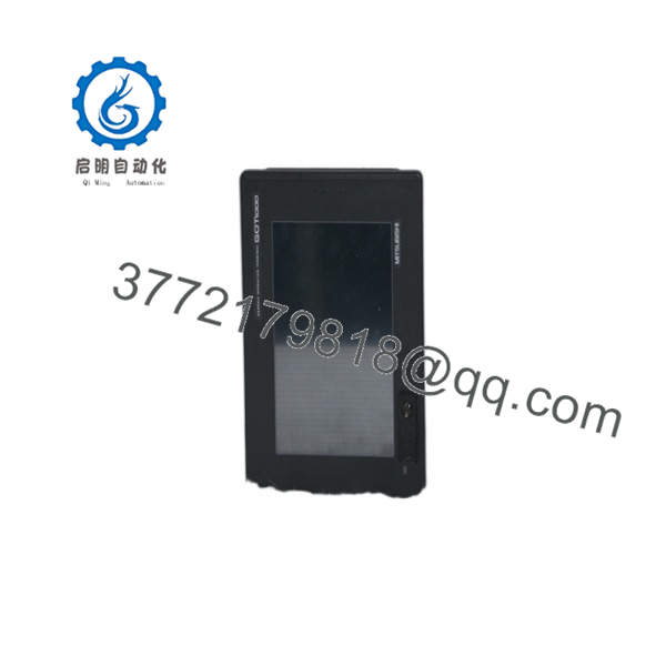
GT1555-VTBD
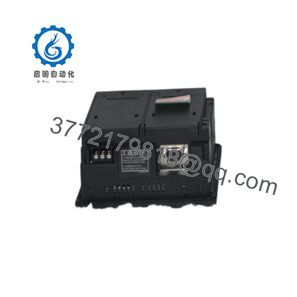
GT1555-VTBD
Technical Pitfall & Survival Guide
❗ 1. GOT1000-to-GOT2000 Replacement Is Not Just a Panel Swap
Mitsubishi identifies GT2705-VTBD and GT2505-VTBD as replacement candidates for , but the manufacturer’s notes identify important differences. For example, CF-card functionality must be migrated to SD card, and communication/option-unit requirements can affect which replacement is appropriate.
Do not order a replacement based only on panel-cut dimensions.
❗ 2. Project Compatibility
The physical HMI and the application project are separate issues.
Before removing the old terminal, determine:
- GT Designer version
- GOT OS version
- Project version
- PLC model
- Communication driver
- Communication interface
- Screen resolution
- External storage requirements
Keep the original project and a copy of the original HMI configuration.
❗ 3. 24 VDC Power Supply
The operates from 24 VDC (+25%, −20%) and has a maximum specified consumption of 19 W, with up to 67 A inrush current for 1 ms at maximum load.
Do not size the supply only from the steady-state wattage. Check the 24 VDC distribution, wiring, fuse protection, and available startup current.
❗ 4. Touchscreen Aging
This model uses a matrix-resistive touch panel. Mitsubishi specifies a touch life of at least 1 million operations under its test conditions.
For surplus inventory, test the entire touch surface rather than checking only the display. A screen can look perfect while individual touch areas have degraded.
❗ 5. Backlight Condition
The uses a cold-cathode fluorescent tube (CCFL) backlight, and Mitsubishi specifies a backlight life of approximately 75,000 hours or longer under its stated conditions. The backlight is not user-replaceable according to the specification.
For a surplus HMI, verify brightness, uniformity, and backlight behavior before installation.
Frequently Asked Questions (FAQ)
Is the Mitsubishi obsolete?
Yes. Mitsubishi Electric lists the as a discontinued product. The manufacturer records an order-end date of March 2017 and a production-end date of April 2017.
For a production machine that still depends on this HMI, keeping one tested spare is worth considering.
What is the display specification of ?
It has a 5.7-inch TFT color LCD, 640 × 480 VGA resolution, and 65,536 colors. The active display area is 115 × 86 mm.
What power supply does use?
The requires 24 VDC, with an allowable range of +25%/−20%. Mitsubishi specifies power consumption of 19 W or less and 14 W or less with the backlight off.
Can I replace with GT2705-VTBD?
Potentially, but do not treat it as a direct plug-and-play replacement. Mitsubishi lists GT2705-VTBD as a replacement candidate and notes panel-cut compatibility, but also documents dimensional and functional differences. Communication units, option units, storage media, and the project itself must be checked.
Will I lose my HMI program when I replace the ?
The project is not automatically transferred simply by installing another HMI. Back up the GOT project before removing the original unit. Also document the OS version, communication configuration, and storage-media contents.
Can be hot-swapped?
Do not assume it can. The HMI uses a 24 VDC power connection and external communication interfaces. Unless the specific installation procedure explicitly permits live replacement, isolate the power before disconnecting the terminal.
What should I check when buying a surplus ?
For a production-critical application, request:
- Photograph of the actual HMI
- Complete nameplate
- Serial number
- Display test
- Full touchscreen test
- Backlight test
- Power-on test
- Communication test
- Connector inspection
- Firmware/OS information
- Condition classification: New Original, New Surplus, or Refurbished/Tested
Mitsubishi has officially discontinued the model, so condition and remaining display/backlight life matter more than simply finding a unit with the correct model number.



