WhatsApp: +86 16626708626
 Email:
 Phone: +86 16626708626
Description
Key Technical Specifications
| Parameter | Specification |
|---|---|
| Manufacturer | Mitsubishi Electric |
| Controller model | CR1-571 |
| Product family | MELFA industrial robot control |
| Maximum simultaneous axes | 6 |
| CPU | 64-bit RISC and DSP, per published controller specifications |
| Robot programming languages | MELFA-BASIC IV or MOVEMASTER COMMAND |
| Program capacity | 88 programs |
| Program position capacity | 2,500 positions |
| Program step capacity | 5,000 steps |
| Standard dedicated I/O | 16 inputs / 16 outputs |
| Maximum I/O expansion | Up to 240 inputs / 240 outputs, depending on configuration |
| Teaching interface | Compatible teaching pendant; exact model must be verified |
| Power input | Depends on the supported robot/controller configuration |
| Communications options | Optional interfaces include Ethernet, CC-Link, and extended serial interfaces |
| Lifecycle | Legacy equipment; current production status requires confirmation |
Source: Mitsubishi Electric’s RV-1A/RV-2AJ Series Standard Specifications Manual (CR1-571 Controller) and related controller documentation. The controller’s supply voltage, I/O configuration, and optional interfaces must be checked against the exact robot model and installed options.
Power supply caution: Mitsubishi’s documentation specifies single-phase 90–132 VAC or 180–253 VAC for certain RV-1A/RV-2AJ and RP-1AH/RP-3AH/RP-5AH configurations, while other configurations use a different specified range. Confirm the controller’s input-voltage setting and nameplate before connecting power.
Product Introduction & Supply Chain Strategy
The Mitsubishi MELFA CR1-571 controls compatible robot motion, program execution, and external I/O in industrial automation systems. Its documented support for MELFA-BASIC IV and MOVEMASTER COMMAND makes the installed program language an important consideration when maintaining an existing robot cell. Optional communication and I/O hardware can also affect how the controller integrates with the rest of the machine.
For spare-parts procurement, verify the robot arm model, controller variant, teaching pendant, interface options, and software version before approving a replacement. A controller that fits the application physically may still require configuration work or fail to support the existing robot and peripherals. Where a failed controller could halt production, compare the cost of a tested spare with the expected downtime and the engineering effort required for a system migration.
Installation & Configuration Guide
Stage 1 — Pre-installation checks
- Record the controller nameplate, input-voltage setting, and hardware configuration.
- Confirm compatibility with the exact robot arm and teaching pendant.
- Back up robot programs, position data, parameters, and relevant I/O assignments.
- Record installed communication options and external interface wiring.
- Review the applicable Mitsubishi controller and robot-arm manuals.
Stage 2 — Remove the existing controller
- Stop the robot using the approved operating procedure.
- Isolate the controller’s electrical supply and apply lockout/tagout.
- Confirm the robot arm and attached tooling are in a safe state.
- Label power, teaching pendant, robot cable, I/O, and communication connections.
- Disconnect and remove the controller according to Mitsubishi’s instructions.
Stage 3 — Install and configure
- Verify the replacement model and input-voltage configuration before wiring.
- Install the controller with the specified grounding and electrical protection.
- Reconnect the robot arm and teaching pendant using the correct cables.
- Restore external I/O and optional interfaces according to the original wiring documentation.
- Restore programs and parameters only after verifying compatibility and backup integrity.
Stage 4 — Power-on and testing
- Inspect grounding, electrical protection, and all connections before energizing.
- Check the controller for initialization errors and abnormal status indications.
- Confirm teaching pendant communication and verify the robot’s reported status.
- Test emergency stops, safety interlocks, external I/O, and communication links.
- Run the approved robot program in a controlled, low-speed mode before resuming automatic production.
Safety note: Do not treat the CR1-571 as a hot-swappable unit. Follow the manufacturer’s shutdown, isolation, and commissioning procedures. Mitsubishi also cautions against switching off controller power during program or parameter rewriting because stored controller information may be damaged.
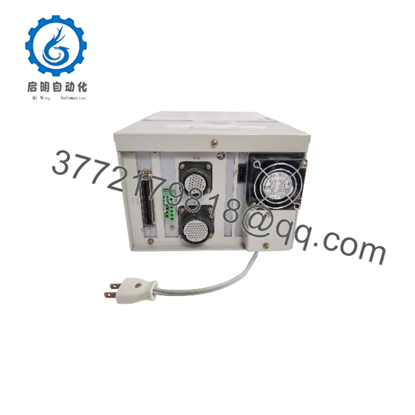
MELFA CR1-571
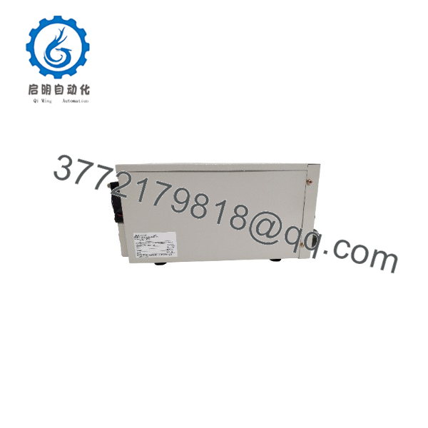
MELFA CR1-571
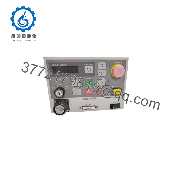
MELFA CR1-571
Firmware, Software Versions & Upgrade Notes
The CR1-571 supports legacy MELFA robot programming and controller-specific engineering functions. Mitsubishi’s controller instruction manual identifies its applicable software versions; the installed version should be recorded before maintenance or replacement.
- Program backup: Back up robot programs, position data, and controller parameters before changing hardware.
- Language compatibility: Verify whether the application uses MELFA-BASIC IV or MOVEMASTER COMMAND.
- Teaching pendant: Confirm the pendant model and firmware compatibility with the controller.
- Optional interfaces: Ethernet, CC-Link, extended serial interfaces, and additional-axis hardware may require specific option modules.
- Parameter restoration: Do not assume that data from a different CR-series controller can be restored without modification.
- Modernization: Evaluate a newer controller only after checking robot-arm compatibility, program conversion requirements, safety circuits, I/O mapping, and communication architecture.
For technical reference, Mitsubishi lists the CR1/CR1B Controller Instruction Manual and CR1/CR2/CR3/CR4/CR7/CR8/CR9 Controller Instruction Manual: Detailed Explanations of Functions and Operations in its documentation library.
Frequently Asked Questions
Q1. What is the Mitsubishi MELFA CR1-571 used for?
It is an industrial robot controller that manages robot motion, program execution, and external I/O for compatible Mitsubishi MELFA robot systems.
Q2. How many axes can the control?
The published controller specification lists up to six simultaneously controlled axes. The supported configuration for a particular installation depends on the robot model and installed options.
Q3. Which robot programming languages does it support?
The documented languages are MELFA-BASIC IV and MOVEMASTER COMMAND. Confirm the installed application’s language and software version before replacing the controller or restoring programs.
Q4. Is the still in production?
It is a legacy controller, and current production availability has not been confirmed. For maintenance planning, verify remaining stock, repair options, and the availability of compatible teaching pendants and cables.
Q5. Can any Mitsubishi MELFA teaching pendant work with it?
No. Compatibility depends on the controller generation, pendant model, and software version. Confirm the exact pendant part number against the applicable Mitsubishi documentation.
Q6. Can a newer Mitsubishi controller replace the directly?
Do not assume direct interchangeability. A modernization project may require a different controller, program conversion, changes to I/O and communication hardware, and a review of safety functions. Confirm compatibility with Mitsubishi or a qualified integrator before selecting an alternative.
Q7. How should New Original or New Surplus condition be verified?
Request photographs of the actual controller, its complete nameplate, and any available serial or date-code information. Obtain written confirmation of condition, testing scope, and warranty terms. New Surplus status should be supported by supplier records rather than inferred from the product’s appearance.