
 WhatsApp: +86 16626708626
 Email:
  Phone: +86 16626708626
Description
3. Key Technical Specifications
| Parameter | Specification / Value |
| Manufacturer | Motorola Computer Group |
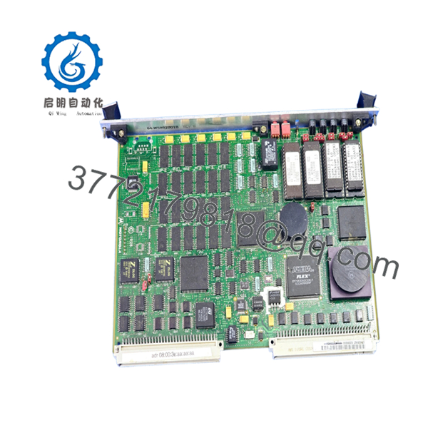
| PCB Assembly Number | 01-W3508F |
| Base Hardware Platform | MVME147 / SMM147 |
| Central Processor | Motorola MC68030 CISC Microprocessor |
| Clock Frequency | 25 MHz |
| Floating Point Unit | MC68882 Coprocessor |
| On-Board DRAM | 16 MB with parity protection |
| Serial I/O Channels | 4 Multiprotocol Serial Ports (SIO via Z8530) |
| Parallel I/O Channels | 1 Centronics-compatible Parallel Port (PIO) |
| Network Controller | AMD Am7990 Local Area Network Controller for Ethernet (LANCE) |
| Storage Interface | Western Digital WD33C93 SCSI Bus Controller |
| Form Factor | Standard Double-Height VMEbus Board |
4. Product Introduction & Supply Chain Strategy
The Motorola 01-W3508F is an intelligent, double-height VMEbus single-board computer utilizing the legacy Motorola MC68030 microprocessor running at 25 MHz. Serving as the primary computational engine for the highly stable MVME147 platform, this board consolidates critical processing, data storage management via a dedicated SCSI interface, and industrial networking over an Am7990 Ethernet controller onto a single physical card. Its native 4-channel serial architecture makes it a preferred master processor for highly deterministic defense processing arrays, older power substations, and maritime propulsion control configurations.
Procuring the 01-W3508F layout as New Surplus is a necessary action for plant managers aiming to stabilize their Total Cost of Ownership (TCO). Because this hardware series has been discontinued by the OEM, the market is saturated with worn-out, refurbished boards that are highly vulnerable to internal component degradation, such as flash memory retention loss or aging clock batteries. Investing in a brand new surplus controller card establishes an optimal insurance policy for your facility. It provides guaranteed zero-hour performance, eliminates the risk of immediate bus timeouts, and bypasses long lead times during emergency plant remediation.

- 01-W3508F
- 01-W3508F
5. Installation & Configuration Guide
Stage 1: Pre-Installation (Prep & Safety)
- De-energize the entire VME chassis following plant lock-out/tag-out (LOTO) protocols to isolate all voltage rails.
- Secure a grounded ESD wrist strap to your body and wire it to a bare metal location on the chassis rack frame to discharge ambient static.
- Remove the old controller card and record all layout elements using a high-resolution camera.
- Document the precise orientation of all jumper settings, specifically those mapping the System Controller (SCON) auto-detect, VMEbus mapping, and base memory addresses.
Stage 2: Removal
- Unthread the upper and lower faceplate locking screws anchoring the module to the rack rails.
- Unlatch the upper and lower injector/ejector handles outward to safely break the pin tension from the VME backplane connectors.
- Slide the card out along the guide tracks smoothly, keeping it perfectly level to prevent contact with neighboring modules. Place it directly inside a static-shielding bag.
Stage 3: Installation (Clone & Seat)
- Modify the hardware jumpers on the new surplus 01-W3508F so they replicate the configuration of the old board down to the individual pin.
- Ensure the memory map configurations on headers match the required memory offset boundaries of your active rack nodes.
- Align the card edges with the slot guides and gently slide the board into the rack until it meets the backplane socket.
- Press both front panel levers inward until the module seats firmly, then fasten the top and bottom screws.
Stage 4: Power-On & Testing
- Re-initialize the primary power supply feeds to the VMEbus rack enclosure.
- Check the system diagnostic LEDs on the front panel faceplate. The CPU, PCI, and SCON lamps must indicate correct runtime states, while the red FAIL indicator must switch off post-boot.
- Establish a terminal link via the asynchronous console port to monitor the internal 147Bug boot monitor handshake and verify the kernel mounts without protocol errors.
6. Firmware/Software Versions & Upgrade Notes
The 01-W3508F assembly executes code via the standard socketed Motorola 147Bug diagnostic firmware monitor. System initialization failures often occur when an asset replacement features a mismatch between the firmware version on the replacement board (e.g., 147Bug V2.44) and the target real-time operating system parameters (e.g., legacy VxWorks driver versions).
Before sliding the new board into place, verify the labels on the socketed EPROMs of your existing unit. If your process requires specific custom drivers to initialize the AMD LANCE network chip or the Western Digital SCSI lines, you must safely remove the physical EPROM chips from the original board using a specialized IC extraction tool and seat them into the corresponding sockets of the new surplus 01-W3508F board. This hardware-level transfer bypasses software translation issues and maintains full system configuration parity.
7. Frequently Asked Questions (FAQ)
Q: Why shouldn’t I just purchase a cheaper refurbished or used 01-W3508F module?
A: Refurbished and second-hand VME cards pose severe operational risks due to thermal stress and component fatigue from decades of continuous use. They often harbor hidden micro-fractures in solder points or degraded capacitors that fail unpredictably under industrial workloads. A failure on a critical DCS control slot can halt production instantly, costing your operation significantly more than what you save on a discounted component. Our New Surplus inventory provides guaranteed zero-hour components that match OEM-level reliability.
Q: Which specific MVME147 model numbers use the 01-W3508F board?
A: The 01-W3508F is the primary printed circuit board assembly (PCBA) code used across several specific configurations of the MVME147 family. It is most commonly found on modules with 16 megabytes of onboard RAM, including the MVME147-010A, MVME147-011A, and MVME147-022A variants. Always verify that your original processor matches these core memory profiles before executing a replacement.
Q: What is the significance of the System Controller (SCON) jumper setting on this card?
A: The SCON setting configuration determines whether the 01-W3508F acts as the master arbiter for the entire VMEbus backplane slot layout. If this card is being placed into Slot 1 of your chassis, the SCON jumper must be enabled (or set to auto-detect). If it is placed in any other slot, SCON must be disabled to prevent severe bus communication collisions and immediate system lock-ups.
Q: Does this board contain any volatile memory backup power sources that require monitoring?
A: Yes. The board features an integrated Time-of-Day (TOD) clock and NVRAM chip backed by an onboard lithium battery cell. During our technical quality audit, we inspect the voltage level of this battery backup system to confirm it meets full factory specifications, ensuring reliable configuration storage parameters and clock tracking for up to 10 years of system standby cycles.
Q: What exact warranty policy applies to this New Surplus product?
A: We provide an absolute 1-year warranty on this Motorola 01-W3508F module. Because this unit is verified New Surplus inventory sourced from secure storage, it contains zero wear on backplane pins and has never been subjected to industrial environments, ensuring a projected active operational lifespan of 10 to 15 years.


