
 WhatsApp: +86 16626708626
 Email:
  Phone: +86 16626708626
Description
3. Key Technical Specifications
| Parameter | Value |
|---|---|
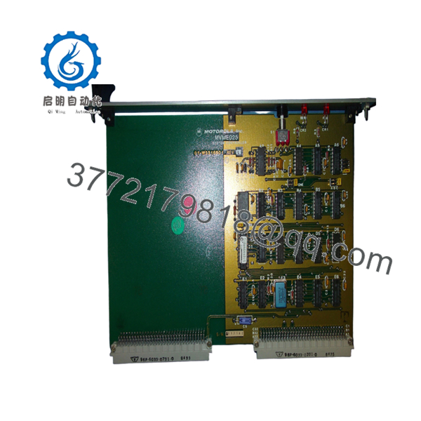
| Model | MVME025 |
| Product Type | VMEbus System Controller |
| Bus Interface | VMEbus |
| System Clock | 16 MHz SYSCLK |
| Bus Arbitration | Priority or Round-Robin |
| Bus Request Levels | 4 Levels |
| Watchdog Timer | Integrated Bus Timeout Logic |
| Power Fail Support | AC Power Fail Detection and Restart Timing |
| Reset Functions | System Reset and System Test Control |
| Power Requirement | +5 VDC, 0.5 A Typical, 0.8 A Maximum |
| Bus Allocation Speed | 100 ns Typical, 130 ns Maximum |
| Operating Temperature | 0°C to +55°C |
| Storage Temperature | -55°C to +85°C |
| Humidity | 8% to 80% Non-Condensing |
| Board Format | Double High Eurocard |
| Dimensions | 234 mm × 160 mm |
| Product Status | Obsolete / Legacy Hardware |
The MVME025 provides arbitration, monitoring, clock generation, reset control, power-fail handling, and watchdog functions required by many VMEbus systems. Motorola designed it as a dedicated system controller rather than a processor module.
4. Product Introduction
The Motorola MVME025 is a VMEbus System Controller Module used to provide critical infrastructure functions within VME-based industrial and embedded computer systems. It generates the system clock, manages bus arbitration, supervises power-fail events, handles reset sequencing, and monitors bus timeout conditions.
Unlike CPU boards such as the MVME120 or MVME147 series, the MVME025 acts as the control backbone of the VME chassis. It is commonly found in legacy industrial automation systems, military electronics, transportation platforms, and scientific instrumentation where VMEbus architectures remain in service.

- MVME025
5. Installation & Configuration Guide
Stage 1: Pre-Installation Preparation (10 Minutes)
⚠️ Safety First
- Notify operations personnel of scheduled downtime.
- Verify all controlled equipment is in a safe state.
- Apply Lock-Out/Tag-Out procedures.
- Remove chassis power.
- Wait a minimum of 5 minutes for stored energy to dissipate.
Tools Required
- ESD wrist strap
- PH1 screwdriver
- Fluke 115 multimeter or equivalent
- Labeling tags
- Smartphone for documentation
- Flashlight
Data Backup
- Record chassis slot assignments.
- Document bus request configurations.
- Photograph:
- DIP switches
- Jumpers
- Backplane connections
- Front-panel indicators
- Record any custom arbitration settings.
Stage 2: Removing the Old Module (5 Minutes)
- Remove retaining screws.
- Label all attached connections.
- Release extraction levers.
- Pull the board straight out.
⚠️ Do not twist the card during removal. Bent VME connectors create intermittent faults that are difficult to diagnose.
- Inspect:
- P1/P2 connectors
- Backplane contacts
- Card guides
- Dust buildup
⚠️ Keep the original board available until startup testing is complete.
Stage 3: Installing the New Module (5 Minutes)
Configuration Clone (Critical)
- Attach ESD protection.
- Verify model number exactly matches MVME025.
- Compare revision labels if present.
- Duplicate all jumper and switch settings.
❗ This is the most common rookie mistake, but it happens constantly. Take a picture before you pull it. I can’t stress this enough.
- Insert the board evenly into the guide rails.
- Seat connectors fully.
- Secure mounting hardware.
Self-Checklist
- Correct model verified
- Jumper settings copied
- Board fully seated
- Connectors inspected
- Retainers secured
Stage 4: Power-On & Testing (10 Minutes)
Pre-Power Check
- Verify +5 V rail integrity.
- Check for shorts using a multimeter.
- Confirm proper grounding.
Power-Up Procedure
- Energize the VME chassis.
- Verify SYSCLK generation.
- Check front-panel indicators.
- Verify arbitration activity.
- Confirm bus timeout functionality.
- Test reset operation.
Functional Verification
- Verify system reset sequence.
- Verify SYSFAIL handling.
- Verify BERR indication.
- Confirm bus request arbitration.
- Check power-fail timing operation.
⚠️ Troubleshooting Note:
- Continuous SYSFAIL indication may indicate a backplane or processor fault.
- Missing SYSCLK often prevents the entire chassis from booting.
- Arbitration failures can appear as random communication timeouts across multiple boards.
6. Frequently Asked Questions (FAQ)
Q1. What exactly does the MVME025 do?
The MVME025 is not a CPU board. It is a VMEbus System Controller that provides system clock generation, bus arbitration, power-fail monitoring, watchdog timing, and reset management for the entire VME chassis.
Q2. Can I run a VME system without an MVME025?
Sometimes, but it depends on the architecture.
Many VME processor boards include limited controller functions. However, multiprocessor and DMA-intensive systems often require a dedicated system controller. Verify system design documentation before removal.
Q3. Is the MVME025 obsolete?
Yes.
The MVME025 belongs to Motorola’s early VMEbus product family and has been out of production for decades. Most available inventory comes from surplus stock or tested legacy equipment suppliers.
Q4. Is this module compatible with MVME120 processor boards?
Yes.
Motorola documentation and legacy support sources indicate the MVME025 was designed for use alongside MVME120-series processor modules and other VMEbus systems requiring centralized arbitration and clock generation.
Q5. Can the MVME025 be hot-swapped?
No.
Power down the chassis before removing or inserting the board. Most VME installations using the MVME025 were not designed for hot insertion. Live replacement risks backplane damage and bus faults.
Q6. What is the most common replacement mistake?
❗ Jumper and arbitration configuration errors.
I’ve seen technicians replace the hardware successfully but forget one arbitration setting. The system then experiences intermittent bus ownership issues that look like CPU failures when the real problem is a simple configuration mismatch.
Q7. Why are some MVME025 units priced significantly below original Motorola pricing?
Because OEM production ended many years ago.
Most units on today’s market are new surplus, refurbished, or recovered from decommissioned systems. Pricing reflects inventory availability rather than historical Motorola list pricing.
Quality Control & Verification Process
Inbound Inspection & Traceability
- Verify OEM labels and part numbers.
- Inspect for:
- Corrosion
- Rework evidence
- Connector wear
- UV discoloration
- Verify serial identification.
- Record inspection results.
Live Functional Testing
- Install the module in a known-good VME test chassis.
- Verify SYSCLK output.
- Verify arbitration operation.
- Test SYSFAIL and BERR indicators.
- Verify watchdog timer functionality.
- Run a continuous 24-hour operational test.
Electrical Testing
- 500 V insulation resistance test (>10 MΩ target).
- Ground continuity verification.
- Power consumption measurement.
- Connector integrity inspection.
Firmware & Configuration Verification
- Document all jumper settings.
- Photograph board configuration.
- Record hardware revision information.
Final QC & Packaging
- QC technician sign-off.
- Anti-static ESD packaging.
- Bubble-wrap protection.
- Heavy-duty corrugated carton.
- QC Passed label with inspection date.
Test photos and operational videos should be available upon request. The objective is to verify the MVME025 functions correctly under load and within a known-good VME environment before shipment.


