WhatsApp: +86 16626708626
 Email:
 Phone: +86 16626708626
Description
Key Technical Specifications
| Parameter | Value |
| Microprocessor | Motorola MC68030 32-bit enhanced processor at 25 MHz |
| Floating-Point Co-processor | MC68882 at 25 MHz |
| Main Memory (DRAM) | 16 MB shared DRAM with programmable parity |
| On-board NVRAM / Clock | 4 KB NVRAM with battery backup (MK48T18 / MK48T02) |
| Firmware Sockets | Four 32-bit wide ROM/PROM/EPROM sockets (up to 4 MB capacity) |
| VMEbus Interface | A32/D32 master/slave interface with system controller functions |
| Communication Interfaces | On-board Ethernet transceiver interface, SCSI bus interface with DMA |
| Serial / Parallel I/O | Four EIA-232-D serial communication ports, Centronics compatible printer port |
| Power Requirements | +5 V DC (3.5 A typical, 5.0 A max), +12 V DC, -12 V DC |
| Board Dimensions | Single-height 6U VME module (233.4 mm x 160.0 mm) |
Product Introduction & Supply Chain Strategy
The Motorola MVME147-013A is a robust, single-board computer built on the VMEbus architecture, integrating a 25 MHz MC68030 processor and 16 MB of parity DRAM. Widely utilized in defense, aerospace, telecommunications, and heavy industrial automation, it combines computing, storage control, and network interfaces onto a single 6U form factor.
Operating legacy systems demands absolute component stability to avoid catastrophic downtime. Procuring this processor board as genuine New Surplus bypasses the hidden risks of refurbished inventory—such as thermally degraded solder joints, oxidized edge connectors, and failing static RAM batteries. Securing an authentic, factory-fresh spare unit protects your long-term maintenance strategy and guarantees dependable operation for mission-critical VME chassis.
Installation & Configuration Guide
1.Pre-Installation (Prep & Safety):Tools needed: ESD wrist strap, flathead screwdriver.
Power down the VME rack completely and disconnect all external AC/DC power feeds. Put on a grounded ESD wrist strap before handling the board. Verify that onboard jumper configurations and EPROM socket contents match your existing system layout.
Verification: Confirm chassis power status lamps are fully off and backplane rails read 0 V DC via multimeter.
2.Removal:Hardware extraction.
Disconnect front-panel cables (Ethernet, serial connectors, or transition module links). Loosen the top and bottom panel retaining screws and carefully slide the MVME147-013A straight out of the VME chassis slot.
Verification: Visually inspect the backplane P1 and P2 connector pins inside the target slot for alignment and absence of debris.
3.Installation (Clone & Seat):Hardware mounting.
Align the edges of the new surplus board with the card guides of the designated VME slot. Push the board straight back until the P1/P2 connectors seat firmly into the backplane, then tighten the front panel screws. Reconnect all communication lines.
Verification: Confirm that the module is completely flush with adjacent cards and securely locked into the rack architecture.
4.Power-On & Testing:System startup.
Restore main power to the VME chassis. Monitor the on-board diagnostic LEDs and console terminal output during the boot sequence to verify kernel initialization and memory check completion.
Verification: Check that the firmware monitor or real-time operating system (RTOS) loads successfully without parity faults or bus timeout errors.
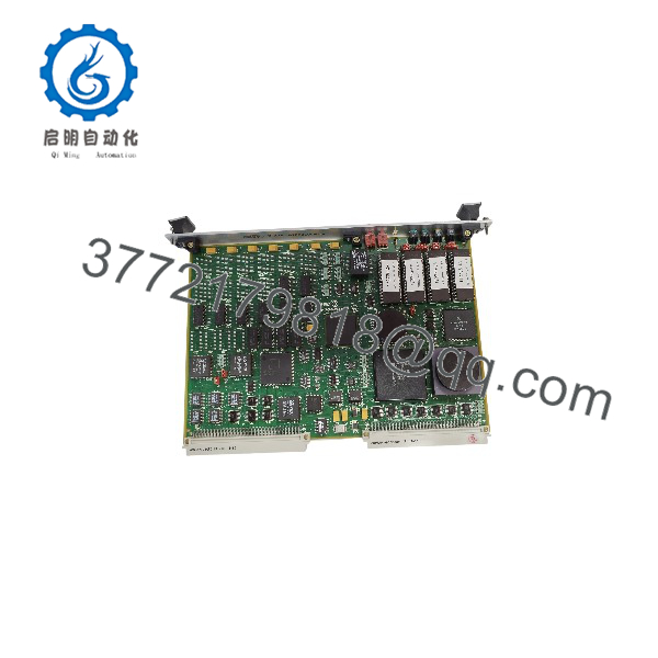
MVME147-013A
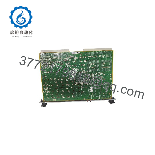
MVME147-013A
Firmware/Software Versions & Upgrade Notes
- Firmware Configuration: Ensure system EPROMs populated in the on-board sockets contain the correct monitor revision (such as MVME147FW) matching your target operating environment (e.g., VxWorks, OS-9, or pSOS+).
- Compatibility Notes: The board requires a compatible VME backplane configuration supporting A32/D32 master/slave transactions and proper termination.
- Upgrade Risk Warning: Never modify EPROM chips or jumper blocks while the rack is powered. Always perform hardware modifications on a static-safe workbench with power fully disconnected to prevent bus driver frying.
Frequently Asked Questions (FAQ)
Is this Motorola MVME147-013A board genuinely new and unused?
Yes. This unit is a Brand New Surplus item, preserved in original packaging with pristine backplane contacts, uncorroded pins, and zero operational service hours.
Why choose New Surplus over refurbished vintage boards?
Vintage computing hardware is highly vulnerable to component aging. Refurbished boards often feature heat-stressed capacitors, brittle traces, and exhausted backup batteries. New Surplus delivers maximum factory longevity and removes the threat of sudden component failure.
What warranty is included with this board?
Every unit includes a comprehensive 1-year replacement warranty, safeguarding your legacy hardware investment.
Can I hot-swap the MVME147-013A in an active VME chassis?
No. VMEbus architecture does not support hot-swapping. You must completely power down the chassis before inserting or extracting single-board computers to prevent severe electrical damage.
How do I manage battery backup replacement for the on-board clock/NVRAM?
The board incorporates an integrated time-of-day clock and NVRAM chip with a self-contained battery. For long-term shelf storage or post-installation service, verify that the battery voltage remains within nominal manufacturer parameters before live deployment.