
 WhatsApp: +86 16626708626
 Email:
  Phone: +86 16626708626
Description
3. Key Technical Specifications
| Parameter | Value |
|---|---|
| Manufacturer | Motorola Computer Group |
| Model | MVME162PA-344SE |
| Product Type | Embedded Controller / Single Board Computer |
| Processor | Motorola MC68040RC33A with FPU |
| CPU Frequency | 32 MHz |
| Memory | 16 MB SDRAM |
| SRAM | 512 KB Battery-Backed SRAM |
| Flash Memory | 1 MB Onboard Flash |
| IndustryPack Support | 4 DMA IndustryPack Ports |
| Serial Ports | 2 × SIO Interfaces |
| Ethernet | Integrated Ethernet Interface |
| SCSI | Integrated DMA SCSI Interface |
| Bus Architecture | ANSI/VITA VMEbus |
| Addressing Support | A16 / A24 / A32 |
| Data Width | D8 / D16 / D32 |
| VME System Controller | Supported |
| Real-Time Clock | Battery-Backed |
| Watchdog Timer | Supported |
| Status LEDs | FAIL, STAT, RUN, SCON, LAN, FUSE, SCSI, VME |
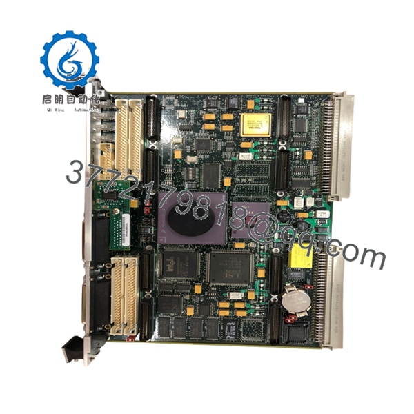
The MVME162PA-344SE is one of the higher-specification MVME162 variants, equipped with a 32 MHz MC68040 processor, 16 MB SDRAM, four DMA-capable IndustryPack interfaces, Ethernet, and SCSI support. Motorola’s cross-reference documentation identifies the “-344SE” configuration as including both Ethernet and SCSI interfaces.
4. Product Introduction
The Motorola MVME162PA-344SE is a VMEbus embedded controller designed for industrial automation, defense electronics, telecommunications infrastructure, semiconductor equipment, and OEM real-time control systems. The board combines a Motorola MC68040 processor, Ethernet networking, SCSI storage support, IndustryPack expansion capability, and VMEbus control functions on a single 6U platform.
In field deployments, the MVME162PA-344SE was often selected where deterministic processing, integrated communications, and flexible I/O expansion were required. The combination of four IndustryPack slots, onboard Ethernet, and SCSI reduced the need for additional VME cards and simplified system architecture.
- MVME162PA-344SE
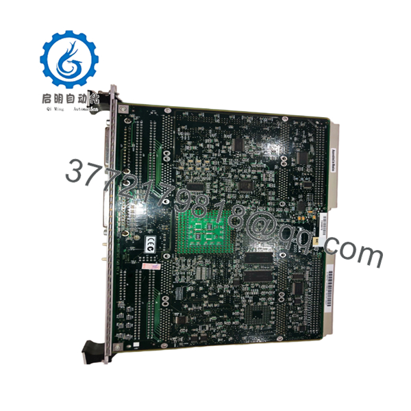
- MVME162PA-344SE
5. Installation & Configuration Guide
Stage 1: Pre-Installation Preparation (10 Minutes)
⚠️ Safety First
- Notify operations of planned downtime.
- Bring the process to a safe operating condition.
- Apply lockout/tagout procedures.
- Remove chassis power.
- Wait at least 5 minutes for capacitor discharge.
Tools Required
- ESD wrist strap
- PH1 screwdriver
- Fluke 115 multimeter
- Cable identification labels
- Smartphone camera
- Flashlight
Data Backup
- Export application software and configuration files.
- Record Ethernet settings and network parameters.
- Document SCSI device IDs and termination settings.
- Photograph all jumper settings.
- Record MVME162BUG firmware revision.
- Document IndustryPack module locations and addresses.
Stage 2: Removing the Old Module (5 Minutes)
- Open chassis access panels.
- Label all cables and transition module connections.
- Disconnect Ethernet and SCSI cabling.
- Remove IndustryPack modules if required.
- Release board retention hardware.
- Operate ejector handles evenly.
⚠️ Never pull from one corner. VME backplane connectors can be damaged by uneven extraction force.
- Remove the board straight out.
- Inspect:
- P1 connector
- P2 connector
- Backplane contacts
- Dust contamination
- Corrosion
- Bent pins
⚠️ Keep the original board available until the replacement passes full functional testing.
Stage 3: Installing the New Module (10 Minutes)
- Attach grounded ESD protection.
- Verify the exact model number:
MVME162PA-344SE
Configuration Clone (Crucial)
- Duplicate all jumper settings.
- Verify Ethernet configuration.
- Verify SCSI configuration and termination.
- Verify IndustryPack module placement.
- Verify VME System Controller settings.
❗ This is the most common rookie mistake, but it happens constantly. Take a picture before you pull it. I can’t stress this enough.
- Insert the board evenly into the VME slot.
- Fully engage ejector handles.
- Tighten retention hardware.
- Reinstall IndustryPack modules.
- Reconnect all cables.
Self-Checklist
- Model verified
- Jumpers duplicated
- IP modules installed
- Ethernet connected
- Board fully seated
Stage 4: Power-On & Testing (15 Minutes)
Pre-Power Check
- Verify no shorts on the +5 V rail.
- Confirm board seating.
- Verify transition module installation.
Power-On Procedure
- Energize the VME chassis only.
- Observe startup LEDs.
- Verify memory count during boot.
- Access MVME162BUG monitor.
- Verify Ethernet communication.
- Verify SCSI device detection.
- Verify serial communications.
- Test IndustryPack I/O operation.
LED Reference
| LED | Function |
|---|---|
| RUN | Processor running normally |
| FAIL | Hardware or boot fault |
| STAT | System status |
| SCON | System Controller active |
| LAN | Ethernet activity |
| SCSI | SCSI activity |
| VME | VMEbus activity |
| FUSE | Fuse monitoring |
These indicators are standard diagnostic tools on MVME162 platforms and are often the fastest way to identify startup issues during commissioning.
⚠️ If the FAIL LED remains illuminated, verify firmware, memory configuration, and jumper settings before replacing hardware.
Common Replacement Risks from the Field
❗ Firmware Revision Mismatch
I’ve seen maintenance teams replace an MVME162 during a shutdown only to spend two days chasing communication faults.
The replacement hardware was healthy.
The problem was a different MVME162BUG firmware revision.
Avoidance: Record the firmware version before removal and request matching firmware when sourcing spares.
❗ DIP Switch and Jumper Misconfiguration
The MVME162PA platform uses multiple jumpers for memory, IndustryPack, VMEbus, and communication settings.
One incorrect jumper can prevent startup.
Avoidance: Photograph every jumper before removal.
❗ IndustryPack Configuration Errors
The MVME162PA-344SE supports four DMA-capable IndustryPack interfaces.
A replacement board may boot normally while attached I/O remains unavailable.
Avoidance: Document every IndustryPack module location and address before shutdown.
❗ Power Draw Specifications
The MVME162 typically requires:
- +5 VDC: 3.5 A typical, 4.5 A maximum
- +12 VDC: 100 mA maximum
- -12 VDC: 100 mA maximum
Additional IndustryPack modules increase total chassis loading.
Avoidance: Calculate total rack power consumption and maintain at least a 20% reserve margin.
❗ Electrostatic Discharge (ESD)
I once watched an engineer swap a 68040 board during a winter outage without a wrist strap.
The board booted successfully.
Two serial channels failed acceptance testing the next day.
That’s an expensive lesson.
Avoidance: Always use a grounded wrist strap and ESD-safe work surface.
Keep these checks in mind and you’ll save yourself 90% of typical rework time.
6. Frequently Asked Questions (FAQ)
Q1. Can I hot-swap the MVME162PA-344SE?
No.
The MVME162 family was not designed for hot-swapping. Removing the controller under power can interrupt VMEbus transactions and potentially damage both the board and the backplane.
Q2. What processor does the MVME162PA-344SE use?
The MVME162PA-344SE uses a Motorola MC68040 processor operating at 32 MHz with an integrated floating-point unit (FPU).
Q3. What does the “344SE” configuration mean?
Motorola cross-reference documentation identifies the configuration as:
- 32 MHz MC68040
- 16 MB SDRAM
- 2 Serial Interfaces
- 4 DMA IndustryPack Ports
- Ethernet Interface
- SCSI Interface
The “SE” suffix indicates inclusion of both Ethernet and SCSI functionality.
Q4. How many IndustryPack modules can be installed?
The MVME162PA-344SE supports four DMA-capable IndustryPack interfaces, allowing expansion with analog I/O, digital I/O, serial communication, motion control, and data acquisition modules.
Q5. Is the MVME162PA-344SE obsolete?
Yes.
The MVME162 family has been out of production for many years. Current availability generally consists of surplus inventory, tested used units, and professionally refurbished hardware.
Q6. What operating temperature is supported?
Motorola documentation specifies operation with forced-air cooling and incoming air temperatures up to approximately 55 °C. System cooling design remains critical for reliable operation.


