
 WhatsApp: +86 16626708626
 Email:
  Phone: +86 16626708626
Description
3. Key Technical Specifications
| Parameter | Value |
| Microprocessor | Motorola MC68040 (32-bit CISC Architecture) |
| Clock Speed | 33.33 MHz |
| Cache Memory | 8 KB Total On-Chip L1 (4 KB Instruction / 4 KB Data) |
| System Memory | 32 MB Extended Error Correction (ECC) DRAM |
| Non-Volatile RAM | 8 KB BBRAM (Battery-Backed NVRAM with Real-Time Clock) |
| On-Board Static RAM | 128 KB SRAM |
| Ethernet Controller | 10 Mbps (Intel i82596CA via AUI interface) |
| SCSI Bus Interface | Narrow SE SCSI (NCR53C710 with DMA support) |
| Serial Ports | 4 Independent Channels (RS-232-D via CD2401 Controller) |
| Parallel Port | 1 Centronics Bidirectional Port |
| Bus Controller | VMEChip2 ASIC (Full A32:D32 Master/Slave, BLT support) |
4. Product Introduction & Supply Chain Strategy
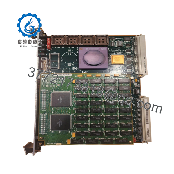
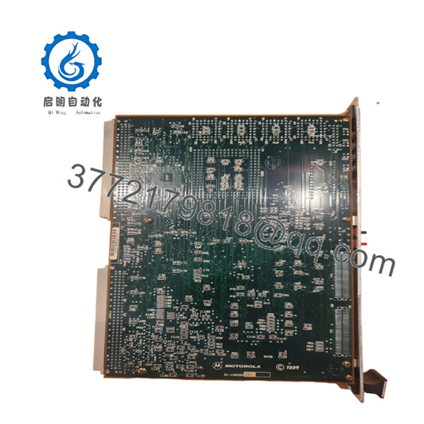
The Motorola MVME167-034B is a highly reliable 6U single-board computer powered by a 33 MHz MC68040 processor with an integrated Floating Point Unit (FPU) and Memory Management Unit (MMU). This computing module features 32 MB of fault-tolerant ECC DRAM and utilizes advanced on-board ASICs, including the VMEChip2 and PCC2, to offload network, SCSI, and serial I/O overhead from the primary processor. It is predominantly used as the central logic engine in critical infrastructure, defense simulation, and heavy industrial automation installations that require strict real-time deterministic performance.
Maintaining operations that rely on legacy VME bus networks demands an aggressive supply chain strategy. Because the MVME167-034B has reached long-term EOL status, relying on the secondary market for refurbished components exposes your plant to high risk due to unverified silicon aging and component degradation. Securing a factory-sealed, New Surplus unit serves as an essential strategic safeguard. This method maintains a low Total Cost of Ownership (TCO) by providing a pristine, zero-hour card ready to handle immediate deployment without the unexpected firmware mismatches or startup faults common to used components.

- MVME167-034B
- MVME167-034B
5. Installation & Configuration Guide
Stage 1: Pre-Installation (Prep & Safety)
- De-energize the target VME chassis and apply standard lock-out/tag-out procedures. Verify all rack-mounted peripheral systems are completely powered down.
- Ensure you are wearing an ESD-safe wrist strap clipped directly to a verified unpainted metal chassis ground point.
- Prior to removing the existing card, use a high-resolution camera to thoroughly document the front-panel cable routes, interface labels, and the configuration of all on-board DIP switches or socketed components.
Stage 2: Removal
- Unfasten the top and bottom captive mounting screws located on the module’s front panel faceplate.
- Carefully disconnect all associated Ethernet, SCSI, serial, and parallel cables from their dedicated front-panel connectors.
- Simultaneously pull the top and bottom injector/ejector handles outward to break the friction fit of the P1 and P2 backplane connections. Slide the board smoothly along the card guides until it clears the chassis, and place it immediately on an ESD-safe conductive mat.
Stage 3: Installation (Clone & Seat)
- Unbox the New Surplus MVME167-034B inside an ESD-protected zone.
- Inspect the configuration jumpers and matching hardware revisions on the new board. Match all localized interrupt, bus-master, and system controller jumper allocations exactly to the original board specifications.
- Slide the card into the matching slot tracks. Push the board evenly into the rack until the connectors meet the backplane. Press both front-panel handles inward simultaneously to seat the pins firmly. Tighten the faceplate captive screws to secure the unit.
Stage 4: Power-On & Testing
- Reconnect all communication lines and peripheral cables back into their verified ports.
- Turn on system power to the VME chassis. Observe the array of eight status LEDs immediately.
- Ensure that the “RUN” indicator activates and the “FAIL” light goes dark after the initial power-on self-test completes. If a boot failure occurs, trace the terminal console output via the serial debug port to capture the 167Bug error codes.
6. Firmware/Software Versions & Upgrade Notes
The MVME167-034B relies on proprietary 167Bug debugging and system initialization firmware resident in four 44-pin PLCC EPROM sockets. It is imperative to check that the ROM code revision level matches your host software requirements (such as VxWorks or specific real-time OS variations) before initiating a production start. Do not attempt to run mixed firmware revisions on multiple boards inside a single backplane mesh, as timing variances between different versions of the VMEChip2 controller can induce protocol bus arbitration timeouts. If your host control program requires a highly customized legacy firmware configuration, transfer the existing operational EPROMs carefully from the failed unit using a dedicated, non-marring PLCC extraction tool.
7. Frequently Asked Questions (FAQ)
- What makes the MVME167-034B variant unique compared to standard MVME167-01 boards?
The “-034B” suffix denotes a highly specific hardware configuration that includes a faster 33 MHz MC68040 processor and 32 MB of high-reliability ECC DRAM memory. Lower-tier boards like the MVME167-001 run at 25 MHz and only carry 4 MB of standard parity memory, making the 034B a significantly more capable computing module for intensive memory and math operations.
- Can I drop this card directly into a slot currently running an older MVME147 board?
While both boards interface with a standard 6U VME backplane, the register configurations, memory mapping, and underlying CPU architecture (MC68030 vs. MC68040) are vastly different. Doing this requires direct modification of the host software application, updating operating system drivers, and auditing your backplane power rail capabilities.
- How does the built-in Error Correction Code (ECC) memory benefit our production facility?
ECC memory actively detects and corrects single-bit memory corruptions in real time, while flagging multi-bit problems. In demanding industrial or high-voltage switchgear environments, electromagnetic interference can induce soft-memory bit flips. This feature keeps the application active and stable, avoiding sudden crashes.
- Is it safe to clear or overwrite the onboard BBRAM data?
The 8 KB BBRAM (MK48T08) holds the persistent real-time clock configuration alongside system parameters utilized by the 167Bug monitor. Overwriting this space through improper diagnostic commands can corrupt the initialization scripts, forcing you to manually reconfigure the board’s boot paths via a serial terminal session.
- What type of warranty covers this obsolete hardware piece?
Every New Surplus MVME167-034B card we ship is backed by a full 1-year functional replacement warranty. We provide immediate shipping options from our specialized safety stock to completely bypass standard supply chain lead times.


