
 WhatsApp: +86 16626708626
 Email:
  Phone: +86 16626708626
Description
3. Key Technical Specifications
| Parameter | Value |
|---|---|
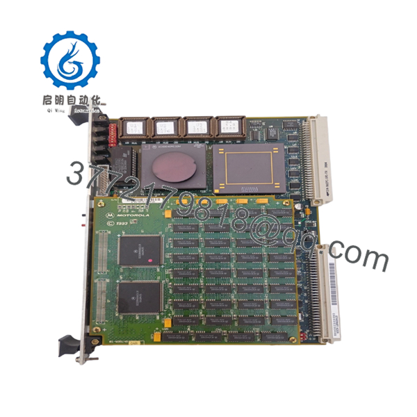
| Manufacturer | Motorola Computer Group |
| Model | MVME167-34A |
| Assembly Number | 01-W38268-34F |
| Product Type | VMEbus Single Board Computer |
| Processor | Motorola MC68040 with FPU |
| CPU Frequency | 33 MHz |
| Bus Architecture | ANSI/VITA VMEbus |
| Form Factor | 6U VME Module |
| Memory Installed | 32 MB ECC DRAM |
| SRAM | 128 KB Battery-Backed SRAM |
| Ethernet | Integrated LAN Interface |
| SCSI Interface | NCR SCSI Controller with DMA |
| Serial Ports | 4 × EIA-232-D Serial Ports |
| Parallel Port | Centronics-Compatible |
| Operating Temperature | 0 °C to 55 °C |
| Storage Temperature | -40 °C to +85 °C |
| Humidity | 5% to 90% Non-Condensing |
| Power Requirement | +5 VDC, +12 VDC, -12 VDC |
The MVME167-34A configuration is documented as a 33 MHz MC68040 VMEbus processor board equipped with 32 MB ECC DRAM, integrated Ethernet, SCSI, serial communications, and DMA capabilities. Part number 01-W38268-34F is listed among known MVME167-34 hardware assemblies.
4. Product Introduction
The Motorola MVME167-34A (01-W38268-34F) is a high-performance VMEbus single-board computer designed for industrial control, defense electronics, telecommunications infrastructure, and embedded OEM equipment. The board combines a 33 MHz Motorola MC68040 processor with integrated communications and storage interfaces on a single 6U VME module.
In field deployments, the MVME167 became one of Motorola’s most widely used VME processors because it combined CPU, Ethernet, SCSI, serial communications, DMA, watchdog functions, and VMEbus control on a single board. Many systems remain operational today because replacing the complete software stack often costs substantially more than maintaining spare MVME167 inventory.

- MVME167-34A 01-W38268-34F
5. Installation & Configuration Guide
Stage 1: Pre-Installation Preparation (10 Minutes)
⚠️ Safety First
- Notify operations personnel of planned downtime.
- Bring the controlled process to a safe state.
- Apply lockout/tagout procedures.
- Remove VME chassis power.
- Wait at least 5 minutes for capacitor discharge.
Tools Required
- ESD wrist strap
- PH1 screwdriver
- Fluke 115 multimeter
- Wire markers
- Smartphone camera
- Flashlight
Data Backup
- Export application software and configuration files.
- Record IP addresses and network settings.
- Photograph all jumper settings.
- Photograph transition module wiring.
- Record boot monitor version.
- Document SCSI device IDs and termination settings.
Stage 2: Removing the Old Module (5 Minutes)
- Remove chassis covers.
- Label all external connections.
- Disconnect transition module cables.
- Release retention hardware.
- Operate both ejector handles evenly.
⚠️ Never twist the board during removal. Bent VME connectors are expensive and difficult to repair.
- Pull the board straight out.
- Inspect:
- P1 connector
- P2 connector
- Backplane contacts
- Dust contamination
- Corrosion
⚠️ Keep the original CPU board until the replacement completes testing successfully.
Stage 3: Installing the New Module (10 Minutes)
- Wear a grounded ESD wrist strap.
- Verify the exact assembly number:
MVME167-34A / 01-W38268-34F
Configuration Clone (Crucial)
- Replicate all jumper settings.
- Verify J2 System Controller configuration.
- Verify J6/J7 serial clock settings.
- Verify SRAM backup power jumper settings.
- Verify transition module compatibility.
❗ This is the most common rookie mistake, but it happens constantly. Take a picture before you pull it. I can’t stress this enough.
- Insert the board evenly into the VME slot.
- Fully engage ejector handles.
- Tighten retaining screws.
- Reconnect all field wiring.
Self-Checklist
- Model number matches
- Jumpers duplicated
- Board fully seated
- Wiring secured
- ESD precautions followed
Stage 4: Power-On & Testing (15 Minutes)
Pre-Power Check
- Verify no shorts exist on the +5 V rail.
- Confirm connector seating.
- Verify transition module installation.
Power-On Procedure
- Power the VME chassis only.
- Observe front-panel LEDs.
- Verify RUN LED activity.
- Verify SCON status if acting as System Controller.
- Connect through console port.
- Verify Ethernet communication.
- Verify SCSI device detection.
- Perform dry-run I/O testing.
LED Reference
| LED | Meaning |
|---|---|
| RUN | CPU executing normally |
| FAIL | Hardware or boot fault |
| SCON | System Controller enabled |
| LAN | Ethernet activity |
| SCSI | SCSI bus activity |
| VME | VMEbus activity |
⚠️ If FAIL remains illuminated, investigate memory, firmware, or jumper configuration before replacing hardware.
Common Replacement Risks from the Field
❗ Firmware Revision Mismatch
I’ve seen maintenance teams install a replacement MVME167 and spend two shifts troubleshooting startup failures.
The board was healthy. The problem was a different firmware revision and altered boot configuration.
Avoidance: Record firmware versions before removal and request matching revisions when ordering.
❗ DIP Switch and Jumper Errors
MVME167 boards contain several critical configuration jumpers.
One incorrect setting can prevent startup.
Avoidance: Photograph every jumper block before removal.
❗ Transition Module Compatibility
Many MVME167 systems use MVME712-series transition modules.
Physical fit does not guarantee signal compatibility.
Avoidance: Verify the complete CPU and transition board combination before installation.
❗ Power Supply Capacity
The MVME167 requires both P1 and P2 VMEbus power connections.
Higher-memory configurations draw noticeably more current than basic models.
Avoidance: Calculate rack power requirements and maintain at least a 20% reserve margin.
❗ Electrostatic Discharge (ESD)
I once watched an engineer remove a 68040 board during a winter shutdown without grounding himself.
The board passed visual inspection but failed memory diagnostics immediately after installation.
Avoidance: Always use ESD protection and handle the board only by its edges.
Keep these checks in mind and you’ll save yourself 90% of typical rework time.
6. Frequently Asked Questions (FAQ)
Q1. Can I hot-swap the MVME167-34A?
No.
The MVME167 family was not designed for hot-swapping. Removing the board under power can interrupt VMEbus transactions and potentially damage the system controller or backplane circuitry.
Q2. What processor does the MVME167-34A use?
The MVME167-34A uses a Motorola MC68040 processor operating at 33 MHz and includes an integrated floating-point unit.
Q3. Is the MVME167-34A obsolete?
Yes.
Motorola discontinued the MVME167 platform many years ago. Most available inventory now comes from surplus stock, decommissioned equipment, or professionally tested refurbishment programs.
Q4. What operating systems can run on this board?
Historically, the MVME167 has been deployed with:
- VxWorks
- OS-9
- pSOS
- LynxOS
- NetBSD
- Proprietary OEM real-time systems
Field users continue operating these platforms in industrial and defense applications today.
Q5. Will I lose my application software during replacement?
Not necessarily.
Most application software resides in flash memory, EPROM devices, SCSI storage, or external boot media. However, always create a complete backup before maintenance activities.
Q6. Why is the P2 connector important?
Unlike some smaller VME processor boards, the MVME167 uses both P1 and P2 connections. The P2 connector carries additional data and addressing signals required for full 32-bit operation.


