
 WhatsApp: +86 16626708626
 Email:
  Phone: +86 16626708626
Description
Key Technical Specifications
| Parameter | Value |
|---|---|
| Processor Family | MPC750-class 32-bit PowerPC (specific clock speed for -0351 suffix — confirm against ordering table; family spans 233/350/450 MHz variants) |
| L1 Cache | 32 KB / 32 KB (instruction/data) |
| L2 Cache | 1 MB backside cache |
| Main Memory | ECC-protected PC100 SDRAM, family capacity range 32 MB to 512 MB (confirm exact capacity for -0351) |
| Flash Memory | 8 MB on-board Flash, user-specified, plus up to 1 MB firmware capacity via two 32-pin PLCC sockets |
| NVRAM / RTC | 8K x 8 NVRAM with time-of-day clock, replaceable battery backup |
| PMC Expansion | Two 32/64-bit PMC slots, IEEE P1386.1 compliant, with front-panel and P2 I/O |
| PCI Expansion | 64-bit PCI expansion mezzanine connector |
| Ethernet | 10/100 Mb/s onboard interface (DEC 21143 controller), routed to front panel via RJ-45 |
| Serial | One asynchronous serial debug port, 16550-compatible UART |
| Timers | Four 32-bit timers, one 16-bit timer, one watchdog timer |
| VMEbus Interface | 4-level requester, 7-level interrupter, 7-level interrupt handler |
| PCI-to-VME Bridge | Universe 2.0 |
| Front Panel Indicators | Fail, CPU, PMC1, PMC2 LEDs plus Reset and Abort switches |
⚠️ Verify the exact clock frequency and SDRAM capacity for the -0351 configuration against Motorola’s MVME2400 ordering guide (form V2400A/IH) or the physical board label before publishing a final spec sheet — ordering-suffix decode wasn’t confirmable with the sources available for this pass, and this family spans a 233–450 MHz range with 32 MB–512 MB memory options.
Product Introduction
The MVME2400-0351-MPC750 is a single-slot VMEbus processor module from Motorola Computer Group, built on Motorola’s PowerPlus II architecture around an MPC750-class PowerPC processor with 1 MB of backside L2 cache. The board pairs the processor with ECC-protected PC100 SDRAM, an 8 MB onboard Flash for user applications, and dual IEEE P1386.1 PMC expansion slots for application-specific I/O — all inside a single VME slot.
Where this earns its keep over a bare CPU board: the dual PMC slots with both front-panel and P2 I/O routing let an integrator add custom analog, digital, or fieldbus I/O without eating a second backplane slot, and the onboard 10/100 Ethernet and asynchronous debug serial port mean you’re not hunting for a separate network interface board. Like most Motorola Computer Group VME product lines, this one has been off active production for years — sourcing today means the surplus channel, and confirming the exact clock speed and memory configuration tied to your specific unit’s suffix matters more here than the headline spec sheet.
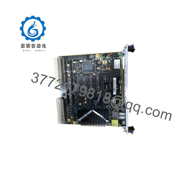
MVME2400-0351-MPC750
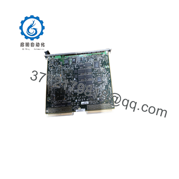
MVME2400-0351-MPC750
Installation & Configuration Guide
Stage 1: Pre-Installation Preparation (~10 min)
⚠️ Safety First: Notify operations of the downtime window, confirm the VME chassis backplane is de-energized, and lock out/tag out chassis power before pulling any board.
Tools Required: ESD wrist strap, PH1/PH2 screwdriver for card-cage injector/ejector handles, digital multimeter, wire labels for PMC/front-panel cabling, smartphone for reference photos.
Data Backup: Record the PPCBug environment settings (MPU clock speed, memory configuration, system controller status, boot device) from the outgoing board before removal. Document PMC module placement in Slot 1 vs. Slot 2, since PMC assignment can be software-addressed.
Stage 2: Removing the Old Module (~5 min)
- Remove the front panel bezel if present.
- Label and disconnect any front-panel Ethernet, serial, or PMC I/O cabling.
- Release the top and bottom card-cage injector/ejector handles.
- Slide the board straight out along its guide rails to protect the VME P1/P2 backplane connectors and the PCI expansion mezzanine connector.
- If PMC modules are installed, note their orientation and slot assignment before removing them from the old board.
⚠️ Keep the old board available until the replacement is confirmed booting — its documented PPCBug environment settings are your primary configuration reference.
Stage 3: Installing the New Module (~15 min)
- ESD prep. Confirm the board is genuinely an MVME2400-0351-MPC750 — other suffixes in the MVME2400 line carry different clock speeds and memory capacities and are not guaranteed performance-equivalent even though the board is physically interchangeable.
- Configuration clone (critical): Re-enter the documented PPCBug environment settings, including system-controller status and memory configuration.
- Transfer or reinstall PMC modules into their original slot positions.
- Slide the board into the guide rails and engage the injector/ejector handles fully — confirm even seating against the P1/P2 backplane and PCI expansion connectors.
- Reattach front-panel Ethernet, serial, and PMC I/O cabling per your labels.
Self-Checklist: [ ] PPCBug environment settings restored [ ] PMC modules seated in correct slots [ ] Cabling reattached per labels [ ] Injector/ejector handles locked
Stage 4: Power-On & Testing (~15 min)
Pre-Power Check: Multimeter check on the backplane supply rails for shorts before re-energizing.
- Power up the chassis and confirm the board boots to the PPCBug debug monitor prompt.
- Verify environment settings, memory size detection, and ECC status match expectations.
- Confirm Ethernet link status via the front-panel RJ-45 and check PMC module enumeration.
- Load and boot the application image (VxWorks, RTEMS, or the original system’s OS image).
- Dry-run test network and PMC I/O before returning the system to production.
⚠️ Troubleshooting Note: If memory size or ECC status reported at boot doesn’t match the documented configuration, suspect a memory module reseating issue or a genuine capacity mismatch against the replacement board’s actual ordering suffix — don’t assume firmware corruption before physically re-checking this.
Frequently Asked Questions (FAQ)
Can the MVME2400-0351-MPC750 be hot-swapped under power?
No. Standard VMEbus boards on this platform aren’t hot-swap rated — de-energize the chassis backplane and lock out power before removing or inserting the board.
Is this model obsolete, and is “new” stock genuinely new?
Yes, obsolete. Motorola Computer Group’s MVME2400 line has been out of active production for a long time, so current supply runs through surplus, pulled, or tested-refurbished channels rather than factory-new builds. State the actual condition of the specific unit rather than a blanket “new” claim.
What’s the direct replacement if this exact suffix is unavailable?
There’s no drop-in modern successor carrying the same PPCBug firmware and VME architecture forward. Buyers typically source another unit within the family (accepting a different clock speed/memory configuration if the application tolerates it) or plan a broader platform migration if long-term supportability is the actual goal.
Will I lose my board configuration when I swap this module?
Yes, unless you document it first. The ‘s PPCBug environment settings and memory configuration live in onboard NVRAM, not on removable media — record the outgoing board’s settings before pulling it, or you’re rebuilding them from scratch.
How do I confirm the exact clock speed and memory size of a specific -0351 unit?
Check the physical label on the board itself and cross-reference it against Motorola’s ordering guide (document V2400A/IH) — the -03xx suffix family spans multiple clock speeds and memory capacities, and I’d recommend confirming this against the physical unit rather than relying on the part number alone until that ordering table is in hand.
Why is your price lower than other “new” listings for this model?
On a board this old, price differences almost always track to testing depth and documented condition rather than a lesser product — an untested pull and a load-tested, NVRAM-battery-verified unit aren’t equivalent even at the same part number. State plainly whether the unit was functionally tested, PMC-slot verified, and what condition applies before quoting.



