WhatsApp: +86 16626708626
 Email:
 Phone: +86 16626708626
Description
Key Technical Specifications
| Parameter | Value |
|---|---|
| Microprocessor | Motorola MPC750 (PowerPC 750) 32-bit RISC, 350 MHz |
| L1 Cache | 32 KB instruction / 32 KB data |
| L2 Cache | 1 MB backside cache |
| Main Memory | 64 MB ECC SDRAM (family supports 32–512 MB ECC) |
| Flash Memory | Up to 9 MB total on-board flash (1 MB firmware + 8 MB user flash) |
| NVRAM / Clock | 8K × 8 NVRAM with time-of-day clock, replaceable battery backup |
| Core Logic | Motorola Hawk ASIC (PCI Host Bridge, MPIC interrupt controller, System Memory Controller) |
| VMEbus Interface | VME64x, 6U, via Tundra Universe II (W83C553) VME-to-PCI bridge; 4-level request/d仲裁 arbitration — verify against datasheet |
| PCI Bus | 33 MHz, 32/64-bit PCI local bus |
| Ethernet | 10/100 Mbps Ethernet (DEC21143 controller), front panel |
| Serial Ports | One asynchronous serial debug port (front panel) |
| Mezzanine Expansion | Two PMC sites (32/64-bit, IEEE P1386.1), front-panel or P2 I/O; plus 64-bit PCI mezzanine connector |
| Timers | Four 32-bit timers, one 16-bit timer, one watchdog timer |
| Debug Monitor | On-board firmware debug monitor with self-test diagnostics (PPCBug firmware family) |
| Endian Support | Big- and little-endian operation (processor/memory and VME domains independently configurable) |
| Form Factor | 6U VME, single slot; MVME2432-1 uses SCANBE ejectors, MVME2432-3 uses IEEE-style (1101-1) handles |
| Power Requirements | ‘+5 V DC via P1/P2; consult the MVME2400-series power table for your configuration |
| Firmware / Boot | Motorola PPCBug / PPC1-Bug |
| OS Support | VxWorks, pSOS+, QNX, Linux for PowerPC, LynxOS, Windows-based RT kernels |
Verify precise parameters against the MVME2400-series Installation and Use manual (V2400A/IH) for your board revision before installation.
Product Introduction
The Motorola MVME2432 is a 6U VME64x processor module from the MVME2400 series, built on Motorola’s PowerPlus II architecture: a 350 MHz MPC750 PowerPC processor, 64 MB of ECC SDRAM, a 1 MB backside L2 cache, and the Hawk ASIC tying the processor, memory, and PCI bus together, with a Tundra Universe II chip bridging to the VME backplane. It serves as a system controller or compute node in embedded VME racks — industrial control, test and measurement, telecom, and defense systems.
The board earns its keep through dual PMC mezzanine slots, which let you add I/O without burning VME slots, and its ECC memory, which corrects single-bit errors before they become unplanned reboots. Since Motorola exited the embedded board business and the line passed to Emerson, the MVME2432 is obsolete with no OEM channel. Maintaining these systems with verified new-surplus boards is far cheaper than a chassis migration.
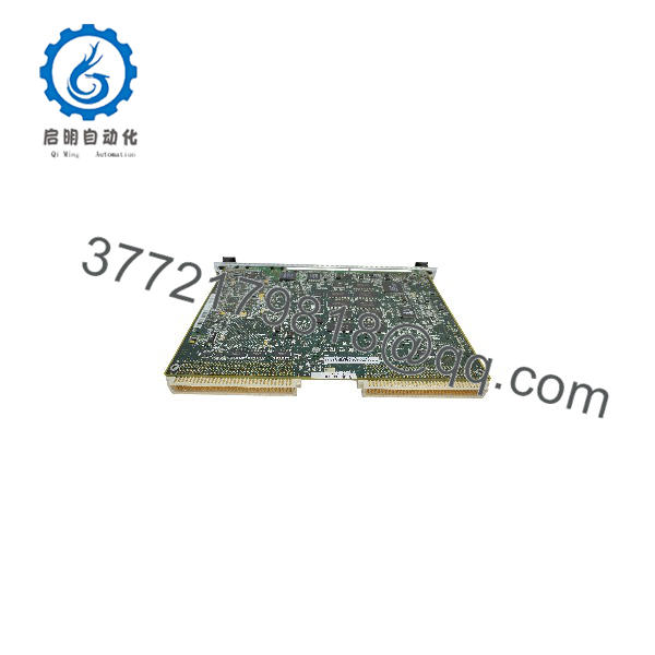
MVME2432
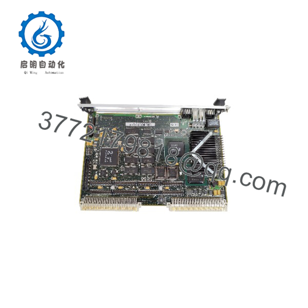
MVME2432
Installation & Configuration Guide
Stage 1: Pre-Installation Preparation (10 minutes)
- ⚠️ Safety First: Notify operations of the downtime window, confirm the system is in a safe state, lock out/tag out chassis power, and wait 5 minutes for backplane capacitors to discharge.
- Tools Required: Grounded ESD wrist strap, ESD mat, PH1 screwdriver, Fluke 115 multimeter (or equivalent), wire labels, smartphone camera.
- Data Backup: Photograph the front panel, all switch/header positions, and cable connections. Record the Ethernet MAC and IP configuration. If the old board still boots, capture the PPCBug banner and firmware revision from the debug serial port (9,600 baud, 8N1) and document the VMEbus address map. Note the system controller configuration — if this board is the VME system controller, the replacement must match it.
- Confirm which variant you need: MVME2432-1 (SCANBE ejectors) or MVME2432-3 (IEEE 1101-1 handles). They are electrically identical but mechanically different; the wrong ejector style can bind in a tight chassis.
- Verify the replacement’s MPC750 revision and PPCBug firmware level against your OS BSP requirements.
Stage 2: Removing the Old Module (10–15 minutes)
- Disconnect front-panel cabling: Ethernet RJ-45, serial debug port. Label each cable.
- If PMC cards are populated with front-panel I/O, disconnect and label those cables too. Note which PMC sits in which slot.
- Loosen the two captive screws top and bottom of the front panel.
- Use the ejector handles and pull the board straight out. Do not rock it side-to-side — that bends P1/P2 backplane pins.
- Inspect the backplane connectors for bent pins and debris; blow out dust with dry, filtered air if needed.
- ⚠️ Note: Keep the old board in an ESD bag on the bench until the replacement is verified running. It’s your fallback.
Stage 3: Installing the New Module (10 minutes)
- Ground yourself at the chassis. Handle the board by the edges only.
- Configuration Clone (Crucial): Compare the new board’s switches and headers against your photos — system controller enable, VMEbus base addresses, endian configuration, console selection. Mirror them exactly. The MPC750 can run big- or little-endian, and a mismatched endian jumper will boot to nothing but silence.
- If your application uses PMC cards, transfer them one at a time, matching slot positions and documenting orientation.
- Verify the front-panel model label and serial number match your invoice.
- Align P1/P2 evenly with the backplane and press firmly until the front panel seats flush. Secure the captive screws.
- Reattach all cabling per your labels.
Self-Checklist: [ ] Switches/headers match photo, [ ] PMC cards seated and matched to slots, [ ] Board fully seated, [ ] Captive screws tight, [ ] All cables reconnected per labels
Stage 4: Power-On & Testing (15–20 minutes)
- Pre-Power Check: Meter the +5 V rail at the backplane for shorts to ground before applying power.
- Power-On Steps:
- Apply chassis power. Leave field devices offline.
- Watch the front-panel LEDs through boot. A clean boot shows the PPCBug banner and self-test diagnostics on the debug serial port (9,600 baud, 8N1).
- Verify the firmware version string matches your records.
- Load your application image; verify the Ethernet link comes up at the correct speed.
- Bring I/O online and run a functional dry-run, including a VMEbus master/slave transfer test if your application depends on backplane DMA.
- ⚠️ Troubleshooting Note: If the board doesn’t reach PPCBug, reseat it first — partial P1 insertion is the most common cause. If PPCBug boots but the OS fails, check the ECC SDRAM mapping against your BSP and confirm the endian configuration. If VME transfers fail but everything else works, revisit the system controller and arbitration settings. If no Ethernet link, check the RJ-45 latch tab and the switch port.
Total estimated time for an experienced technician: 45–55 minutes, including functional verification.
Frequently Asked Questions (FAQ)
Q: Can I hot-swap the MVME2432 under power?
No. The MVME2400 series is not a live-insertion design. Pulling it hot risks backplane transients that can damage adjacent boards — and if this board is the VME system controller, yanking it mid-arbitration can hang the whole chassis. Kill the power, meter the rails, then pull it. The 5-minute capacitor wait annoys everyone, but I’ve seen a rushed hot-pull take out a neighboring I/O board. Not worth it.
Q: Is this model obsolete, and are your units genuinely new?
Yes — the MVME2432 is obsolete. Motorola Computer Group exited the embedded board business years ago and the line passed to Emerson Network Power; no OEM manufacturing channel remains. Our units are New Original / New Surplus: factory-built boards held in distributor or OEM spares inventory, never deployed, with inbound traceability records. Refurbished, fully load-tested boards are also available at lower cost, clearly labeled as such. We never mix conditions.
Q: What’s the difference between -1 and -3?
Electrically identical — both are 350 MHz MPC750 with 64 MB ECC SDRAM. The difference is mechanical: the -1 ships with SCANBE ejectors, the -3 with IEEE 1101-1-style handles. If you’re replacing an existing board in a tightly packed chassis, match the variant exactly; front-panel hardware can bind or leave gaps otherwise. Tell us which one your chassis uses when ordering.
Q: What is the direct replacement if the MVME2432 is out of stock?
Within the same series, the MVME2431 (32 MB ECC) and MVME2433 (128 MB ECC) share the identical architecture, processor, and PMC layout — a memory-size difference your BSP can usually accommodate. If you need a growth path, the MVME5100 series offers newer PowerPC processors in the same 6U form factor, but it is not drop-in: different processor generation, firmware, and BSP rebuild required. If your application software can’t be easily rebuilt, sourcing another MVME2432 or sibling variant is the lower-risk path. Ask us about current stock on both.
Q: Will I lose my application software when I pull the old board?
Depends on where the image lives. If it boots from the on-board user flash (8 MB), back it up before removal — connect via the debug serial port and PPCBug, and copy the image to a host. If it loads over the network at boot (common with VxWorks setups), the new board pulls it down unchanged. Either way, confirm before pulling anything. If you have no copy of the application image or its source, do not remove the board until you do — recovering a dead flash with no backup is a very bad week.
Q: Why is your price lower than the original OEM list price?
OEM list price reflected active production, which no longer exists. New-surplus stock was bought years ago at volume pricing and held in inventory. The hardware is identical factory production. What you give up is OEM warranty and support — which we replace with our own QC process and a 1-year replacement warranty.
Q: Do you test the boards before shipping?
Yes, every unit — new surplus or refurbished — goes through the same process: inbound inspection with serial-number verification and anti-counterfeit checks, power-up on a genuine VME test chassis with a known-good backplane, PPCBug boot and self-test verification, ECC SDRAM memory test, Ethernet link and throughput test, serial port loopback, VMEbus transfer test, and a minimum 24-hour continuous burn-in with thermal monitoring. You receive the test report with your board, and power-on photos or video for your specific serial number are available before shipment.