
 WhatsApp: +86 16626708626
 Email:
  Phone: +86 16626708626
Description
3. Key Technical Specifications
| Parameter | Value |
|---|---|
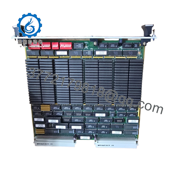
| Model | MVME246-3 |
| Manufacturer | Motorola |
| Product Type | VMEbus Memory Module |
| Form Factor | 6U VMEbus Single-Slot Board |
| Bus Interface | VMEbus |
| Slot Requirement | Single Slot |
| Front Panel Indicator | LED Power Indicator |
| Installation Type | VME Rack Mounted |
| Application | Memory Expansion / Shared Memory Functions |
| Cooling Method | Chassis Airflow Dependent |
| Product Status | Obsolete Legacy Hardware |
| Typical Industries | Industrial Automation, Defense, Scientific Systems |
| Board Family | MVME VMEbus Platform |
The MVME246-3 is identified as a dedicated VME Memory Module rather than a processor board. It was designed for VMEbus systems requiring additional memory resources within legacy Motorola-based architectures.
4. Product Introduction
The Motorola MVME246-3 is a VMEbus memory module designed for installation in standard 6U VME racks. Unlike CPU boards such as the MVME167 or MVME197 series, the MVME246-3 provides memory resources to support embedded computing systems, industrial controllers, and OEM equipment built around the VMEbus architecture.
Engineers typically source this board when maintaining long-life systems where replacing the original hardware avoids expensive software validation or complete control-system migration. In many legacy VME installations, obtaining the correct memory module is considerably less disruptive than redesigning the entire platform.
- MVME246-3
5. Installation & Configuration Guide
Stage 1: Pre-Installation Preparation (10 Minutes)
⚠️ Safety First
- Notify operations of planned downtime.
- Verify equipment is in a safe operating state.
- Apply Lock-Out/Tag-Out procedures.
- Remove chassis power completely.
- Wait at least 5 minutes for capacitor discharge.
Tools Required
- ESD wrist strap
- PH1 screwdriver
- Fluke 115 multimeter
- Wire labels
- Smartphone for documentation
- Flashlight
Data Backup
- Record VME slot location.
- Document system memory configuration.
- Photograph:
- Board location
- Jumper settings
- Rear transition modules
- Chassis layout
- Record CPU and operating system information.
Stage 2: Removing the Old Module (5 Minutes)
- Remove retaining hardware.
- Label any associated connections.
- Release ejector handles.
- Pull the board straight out using even pressure.
⚠️ Never twist a VME board during extraction. Connector damage often causes intermittent memory faults that are difficult to troubleshoot.
- Inspect:
- P1 connector
- P2 connector
- Guide rails
- Backplane pins
⚠️ Retain the old board until commissioning is complete.
Stage 3: Installing the New Module (5 Minutes)
Configuration Clone (Critical)
- Connect ESD protection.
- Verify exact model number:
- MVME246-3
- Board revision
- Assembly number
- Duplicate all jumpers and switches.
❗ This is the most common rookie mistake, but it happens constantly. Take a picture before you pull it. I can’t stress this enough.
- Insert the board into the card guides.
- Seat connectors fully.
- Secure ejector handles and screws.
- Verify proper board alignment.
Self-Checklist
- Model verified
- Jumpers duplicated
- Connectors seated
- Retainers locked
- Slot position confirmed
Stage 4: Power-On & Testing (10 Minutes)
Pre-Power Check
- Measure power rails for shorts.
- Verify chassis grounding.
- Inspect airflow paths.
Power-On Steps
- Power the VME rack only.
- Observe power LED.
- Verify CPU startup.
- Check memory recognition.
- Confirm system diagnostics pass.
- Restore application software if required.
Functional Verification
- Verify memory access.
- Check VMEbus communication.
- Execute memory diagnostics.
- Run system under load.
- Monitor temperature stability.
⚠️ Troubleshooting Note:
- Memory parity errors may indicate incompatible memory revisions.
- Bus timeout alarms often point to addressing conflicts.
- Failure to boot may indicate incorrect slot assignment or configuration mismatch.
Technical Pitfall & Survival Guide
❗ Firmware Revision Mismatch
I’ve seen maintenance teams replace a VME memory board only to discover the CPU firmware expected a different memory map.
The replacement hardware wasn’t faulty. The firmware simply didn’t recognize the installed memory configuration.
Avoidance:
- Record firmware versions before shutdown.
- Verify supported memory configurations.
- Request matching hardware revisions when ordering.
❗ DIP Switch and Jumper Configuration
Memory addressing often depends on jumper settings.
A single incorrect jumper can create overlapping address ranges that appear as random system crashes.
Avoidance:
- Photograph every jumper.
- Compare old and replacement boards side-by-side.
- Verify address assignments.
❗ Backplane Compatibility
Even within Motorola VME families, system configurations can vary.
Warning: Never assume compatibility based solely on similar part numbers.
Avoidance:
- Verify chassis documentation.
- Confirm VME addressing requirements.
- Review OEM manuals before installation.
❗ Power Consumption Margins
Memory expansion boards increase rack loading.
For older VME systems operating near power-supply limits, adding or replacing modules can expose existing power issues.
Avoidance:
- Calculate rack consumption.
- Maintain at least 20% spare power capacity.
- Verify cooling performance.
❗ Electrostatic Discharge (ESD)
I once watched an engineer remove a VME memory board during winter without an ESD strap.
The board passed inspection, installed normally, and failed two hours later during operation.
The root cause was static damage.
Avoidance:
- Wear a grounded wrist strap.
- Use an ESD mat.
- Store boards in anti-static packaging.
Keep these checks in mind and you’ll save yourself 90% of typical rework time.
6. Frequently Asked Questions (FAQ)
Q1. What does the MVME246-3 actually do?
The MVME246-3 is a VMEbus memory module designed to provide memory resources within Motorola-based VME systems. It is not a processor board.
Q2. Is the MVME246-3 obsolete?
Yes.
The board belongs to a legacy Motorola VME product family that has been out of production for many years. Most available inventory comes from surplus stock, refurbished equipment, or decommissioned systems.
Q3. Can I hot-swap this module?
No.
Most VMEbus systems using boards of this generation were not designed for hot insertion. Removing the board under power can disrupt bus operations and damage hardware.
Q4. How can I verify compatibility before ordering?
Check:
- MVME246-3 part number
- Assembly number
- Hardware revision
- Chassis model
- CPU model
- Operating system
- Existing memory configuration
Always verify against the system documentation.
Q5. Why is it difficult to find complete specifications?
Many Motorola VME products entered the market decades ago. Original documentation is often unavailable, and surviving systems frequently use custom OEM configurations.
Q6. Why are surplus units still valuable?
Because replacing a failed memory module often costs far less than redesigning a legacy control platform.
In industrial automation, semiconductor manufacturing, and transportation systems, software migration can require months of validation.
Q7. Why is pricing so different between suppliers?
Condition is the primary factor.
A tested board with documented burn-in results, inspection records, and warranty coverage typically commands a higher price than an untested pull from surplus inventory.
Quality Control & Verification Process
1. Inbound Inspection & Traceability
- Verify OEM labels and assembly numbers.
- Confirm source documentation.
- Inspect for:
- Corrosion
- Scratches
- Rework marks
- UV yellowing
- Audit included accessories.
2. Live Functional Testing
- Install in a known-good VME test chassis.
- Verify power-up operation.
- Confirm VMEbus communication.
- Execute memory diagnostics.
- Run continuous operation for 24+ hours.
- Generate an official test report.
3. Electrical Parameter Testing
- 500 V insulation resistance test (>10 MΩ target).
- Ground continuity verification.
- Power rail measurements.
- Connector integrity inspection.
4. Firmware & Configuration Verification
- Document hardware revision.
- Photograph jumper settings.
- Record memory configuration.
- Archive installation settings.
5. Final QC & Packaging
- QC inspector sign-off.
- Anti-static ESD bagging.
- Bubble-wrap protection.
- Heavy-duty corrugated carton.
- QC Passed label with inspection date.
Test photos and operational videos should be available upon request. For legacy VME hardware, the objective is not to promise failure-free operation but to verify that the module functions correctly under controlled load testing before shipment.


