
 WhatsApp: +86 16626708626
 Email:
  Phone: +86 16626708626
Description
3. Key Technical Specifications
| Parameter | Value |
|---|---|
| Product Model | MVME332XTS |
| Part Number | 01-W3822B-01D |
| Bus Architecture | VMEbus |
| Processor | Motorola MC68010 |
| CPU Clock Speed | 12 MHz |
| Coprocessor | MC68230, 10 MHz |
| SRAM | 256 KB |
| EPROM | 128 KB |
| Communication Channels | 8 |
| Serial Interface | RS-232C |
| Communication Modes | Synchronous and Asynchronous |
| Dynamic RAM | 128 KB, expandable to 512 KB |
| I/O Access | Front Panel and P2 Connector |
| Operating Role | Intelligent Communications Controller |
Technical specifications above are compiled from available MVME332XT family documentation and field references. Verify exact revision compatibility before installation.
4. Product Introduction
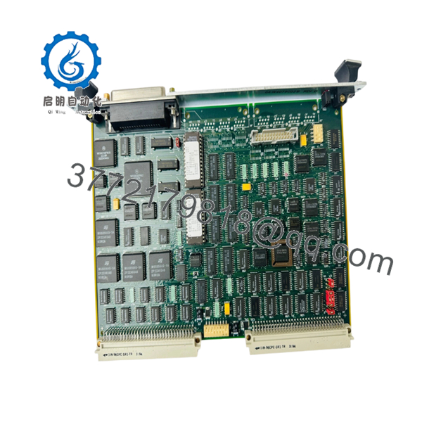
The Motorola MVME332XTS 01-W3822B-01D is a VMEbus intelligent communications controller designed for industrial control systems, telecommunications equipment, and embedded computing platforms requiring multiple serial communication channels. It belongs to the MVME332XT family and provides eight RS-232 communication ports managed by an onboard MC68010 processor.
Engineers commonly deploy this board in legacy VME racks where deterministic serial communications remain critical. The onboard processor offloads communication handling from the host CPU, reducing system overhead in multi-device environments.

- Motorola MVME332XTS 01-W3822B-01D
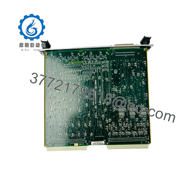
- Motorola MVME332XTS 01-W3822B-01D
5. Installation & Configuration Guide
Stage 1: Pre-Installation Preparation (10 Minutes)
⚠️ Safety First
- Notify operations personnel of planned downtime.
- Verify the process is in a safe operating state.
- Apply lockout/tagout procedures.
- Remove rack power completely.
- Wait at least 5 minutes for power supply capacitors to discharge.
Tools Required
- ESD wrist strap
- PH1 screwdriver
- Fluke 115 or equivalent multimeter
- Wire markers
- Smartphone or camera
- Flashlight
Data Backup
- Export controller configuration files.
- Document node addresses and communication settings.
- Photograph all cabling.
- Photograph switch, jumper, and termination settings.
- Record existing firmware revision if accessible.
Stage 2: Removing the Old Module (5 Minutes)
- Remove front panel retaining screws.
- Label all communication cables before disconnecting.
- Disconnect serial and transition-module connections carefully.
- Release VME card ejector handles.
- Pull the board straight out of the backplane.
⚠️ Note
Keep the original board available until the replacement has completed operational testing. It often becomes the fastest reference when troubleshooting address or jumper discrepancies.
Inspection
- Check for bent VME backplane pins.
- Remove dust contamination.
- Inspect card guides for damage.
Stage 3: Installing the New Module (10 Minutes)
Critical Steps
- Attach ESD strap before handling the board.
- Verify model number exactly matches MVME332XTS 01-W3822B-01D.
- Clone all jumper and switch settings from the original board.
This is the most common rookie mistake, but it happens constantly. Take a picture before you pull it. I can’t stress this enough.
- Insert the board evenly into the VME card guides.
- Seat the board fully into the backplane connector.
- Lock ejector handles.
- Reconnect all cables according to documented labels.
Self-Checklist
- Model number verified
- Jumper settings duplicated
- Node address verified
- Wiring reconnected
- Board fully seated
- ESD procedures followed
Stage 4: Power-On & Testing (10 Minutes)
Pre-Power Check
- Measure 24 V supply rails.
- Check for shorts between power and ground.
- Verify rack power supply health.
Startup Procedure
- Power the VME rack only.
- Observe startup LEDs.
- Verify board initialization.
- Confirm host CPU detects the module.
- Test serial communication channels individually.
- Verify communication handshake with connected devices.
- Conduct loopback testing where possible.
⚠️ Troubleshooting Note
- Solid fault indication after installation frequently points to firmware incompatibility.
- No communication typically indicates addressing, cabling, or termination errors.
- If the host system fails to enumerate the board, reseat the module and inspect backplane connectors.
6. Frequently Asked Questions (FAQ)
Q1. Can I hot-swap the MVME332XTS?
No.
This board was designed for traditional VMEbus systems where hot insertion is generally not supported. Removing or inserting the board under power can damage the module or backplane. Shut the rack down completely before replacement.
Q2. Is the MVME332XTS obsolete?
Yes.
The MVME332XT family is a legacy Motorola VMEbus platform that has been out of mainstream OEM production for many years. Most available inventory comes from surplus stock, refurbished units, or recovered industrial systems.
Q3. Is this board genuinely new?
That depends on inventory source.
In the surplus automation market you will typically encounter:
- New Original (surplus inventory)
- New Surplus
- Refurbished (tested)
- Used pull-outs
Always request actual photographs, test reports, and serial-number documentation before purchasing.
Q4. Will I lose my application logic if I replace this board?
Normally no.
The MVME332XTS functions as a communications controller rather than the primary system CPU. Application software generally resides on the host processor. However, communication parameters and addressing should be documented before replacement.
Q5. What is the direct replacement if this model is unavailable?
The safest replacement is the identical part number:
- MVME332XTS 01-W3822B-01D
Other MVME332XT-family revisions may appear physically similar, but firmware, connector options, and revision-level differences should be verified before installation. I’ve seen projects lose an entire weekend because someone assumed two nearly identical Motorola boards were interchangeable.
Q6. Why do communication failures occur after a successful board replacement?
The most common causes are:
- Firmware revision mismatch.
- Incorrect jumper settings.
- Wrong node address.
- Termination resistor configuration errors.
- Damaged serial cables.
I’ve seen a technician spend two days chasing a “bad board” that was actually configured for the wrong serial address.
Q7. What warranty should I expect?
For surplus industrial electronics, a 6- to 12-month warranty is common. Many tested inventory suppliers currently offer one-year warranties on MVME332XT-family hardware. Review warranty terms carefully because coverage often excludes installation errors and ESD damage.
Technical Pitfall & Survival Guide
❗ Firmware Revision Mismatch
Document firmware before removal.
I’ve seen communication controllers replaced with newer revisions that appeared identical. The hardware powered up normally, but the host repeatedly reported communication timeouts. The root cause was a firmware change between revisions.
Avoidance: Record firmware version and request matching revisions when ordering.
❗ DIP Switch / Jumper Misconfiguration
This is the most common field mistake.
Many communication faults originate from incorrect node addresses or termination settings.
Avoidance: Photograph every switch and jumper before removing the original board.
❗ Terminal Block / Wiring Differences
Never assume connector assignments remain identical across revisions.
Even similar VME communication cards can introduce wiring differences.
Avoidance: Verify against the wiring diagram, not memory.
❗ Power Budget Problems
Legacy VME systems often operate close to supply limits.
A replacement board may draw slightly different current than the failed unit.
Avoidance: Calculate total rack loading and maintain at least a 20% power margin.
❗ Electrostatic Discharge (ESD)
I once watched an engineer handle a communications board during winter without an ESD strap. The board powered up once and never again.
Avoidance: Use a grounded wrist strap and ESD-safe work surface at all times.
Keep these checks in mind and you’ll save yourself 90% of typical rework time.


